John Logie Baird (1888-1946)
Baird Televisor
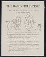
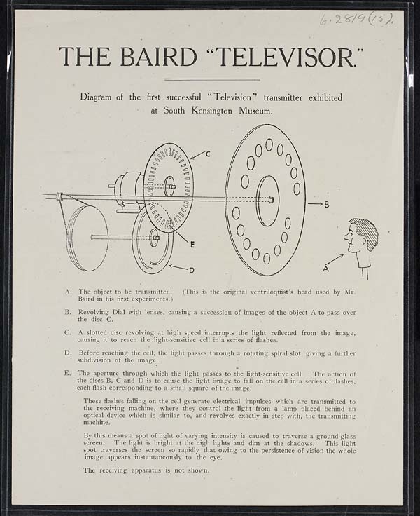
THE BAIRD “TELEVISOR.”
=======================
Diagram of the first successful “Television” transmitter exhibited
at South Kensington Museum.
[NLS note: a graphic appears here – see image of page]
A. The object to be transmitted. (This is the original ventriloquist’s head used by Mr.
Baird in his first experiments.)
B. Revolving Dial with lenses, causing a succession of images of the object A to pass over
the disc C.
C. A slotted disc revolving at high speed interrupts the light reflected from the image,
causing it to reach the light-sensitive cell in a series of flashes.
D. Before reaching the cell, the light passes through a rotating spiral slot, giving a further
subdivision of the image.
E. The aperture through which the light passes to the light-sensitive cell. The action of
the discs B, C and D is to cause the light image to fall on the cell in a series of flashes,
each flash corresponding to a small square of the image.
These flashes falling on the cell generate electrical impulses which are transmitted to
the receiving machine, where they control the light from a lamp placed behind an
optical device which is similar to, and revolves exactly in step with, the transmitting
machine.
By this means a spot of light of varying intensity is caused to traverse a ground-glass
screen. The light is bright at the high lights and dim at the shadows. This light
spot traverses the screen so rapidly that owing to the persistence of vision the whole
image appears instantaneously to the eye.
The receiving apparatus is not shown.
- © National Library of Scotland 2009
- NLS home page
- Digital library