Encyclopaedia Britannica > Volume 3, Anatomy-Astronomy
(422) Page 414
Download files
Complete book:
Individual page:
Thumbnail gallery: Grid view | List view
414
Arch.
Effects of
cement
and fric¬
tion in
dome¬
vaulting.
The iron
bridge at
Sunder¬
land de¬
scribed.
ARCH.
course, and then a similar or a greater portion of a small¬
er sphere may spring from this course as a base. It also
bears being intersected by cylindrical vaultings in every
direction, and the intersections are exact circles, and al¬
ways have a pleasing effect. It also springs most grace¬
fully from the heads of small piers, or from the corners
of rooms of any polygonal shape; and the arches formed
by its intersections with the walls are always circular and
graceful, forming very handsome spandrels in every posi¬
tion. For these reasons Sir Christopher Wren employed
it in all his vaultings, and he has exhibited many beauti¬
ful varieties in the transepts and the aisles of St Paul s,
which are highly worthy of the observation of architects.
Nothing can be more graceful than the vaultings at the
ends of the north and south transepts, especially as fur¬
nished off in the fine inside view published by Gwynn and
Wale.
46. The connection of the parts arising from cement and
from friction has a great effect on dome-vaulting. In the
same way as in common arches and cylindrical vaulting, it
enables an overload on one place to break the dome in a
distant place. But the resistance to this effect is much
greater in dome-vaulting, because it operates all round
the overloaded part. Hence it happens that domes are
much less shattered by partial violence, such as the fall¬
ing of a bomb or the like. Large holes may be broken in
them without much affecting the rest; but, on the other
hand, it greatly diminishes the strength which should be
derived from the mutual pressure in the vertical joints.
Friction prevents the sliding in of the arch-stones, which
produces this mutual pressure in the vertical joints, except
in the very highest courses, and even there it greatly di¬
minishes it. These causes make a great change in the
form which gives the greatest strength ; and as their laws
of action are as yet but very imperfectly understood, it is
perhaps impossible, in the present state of our knowledge,
to determine this form with tolerable precision. We see
plainly, however, that it allows a greater deviation from
the best form than the other kind of vaulting, and domes
may be made to rise perpendicular to the horizon at the
base, although of no great thickness; a thing which must
not be attempted in a plain arch. The immense addition
of strength which may be derived from hooping largely
compensates for all defects; and there are hardly any
bounds to the extent to which a very thin dome-vaulting
may be carried when it is hooped or framed in the direc¬
tion of the horizontal courses. The roof of the Halle du
Bled at Paris is but a foot thick, and its diameter is more
than 200, yet it appears to have abundant strength. It
is, on the whole, a noble specimen of architecture.
47. We must not conclude this article without taking
notice of that magnificent and elegant arch erected in
cast iron at Wearmouth, near Sunderland, in the county
of Durham. The inventor and architect was Rowland
Burden, Esq.
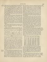
This arch (of which a view is given at the article Bridge)
is a segment of a circle whose diameter is about 444 feet.
The span or chord of the arch is 236 feet, and its versed
sine or spring is 34 feet. It springs at the elevation of
60 feet from the surface of the river at low water, so that
vessels of 200 or perhaps 300 tons burden may pass under
it in the middle of the stream, and even 50 feet on each
side of it.
The sweep of the arch consists of a series of frames of
cast iron, which abut on each other, in the same manner
as the voussoirs of a stone arch. One of these frames or
blocks (as we shall call them in future) is represented in
Plate XLIX. fig. 3, as seen in front. It is cast in one piece,
and consists of three pieces or arms BC, BC, BC, the middle
one of which is two feet long, the upper being somewhat Arch,
more, and the lower somewhat less, because their extiemi-'v-^~v^
ties are bounded by the radius drawn from the centie of the
arch. These arms are four inches square, and are con¬
nected by other pieces KL, of such length that the whole
length of the block is five feet in the direction of the
radius. Each arm has a flat groove on each side, which
is expressed by the darker shading, three inches broad
and three fourths of an inch deep. A section of this
block, through the middle of KL, is represented by the
light-shaded part BBB, in which the grooves are more
distinctly perceived. These grooves are intended for re¬
ceiving flat bars of malleable iron, which are employed for
connecting the different blocks with each other. Fig. 4
represents two blocks united in this manner. For this
purpose each arm has two square bolt-holes. The ends
of the arms being nicely trimmed off, so that the three
ends abut equally close on the ends of the next block ; and
the bars of hammered iron being also nicely fitted to their
grooves, so as to fill them completely, and have their bolt¬
holes exactly corresponding to those in the blocks; they
are put together in such a manner that the joints or meet¬
ings of the malleable bars may fall on the middle between
the bolt-holes in the arms. Flat-headed bolts of wrought
iron are then put through, and keys or forelocks are driven
through the bolt-tails, and thus all is firmly wedged to¬
gether, binding each arm between two bars of wrought
iron. These bars are of such length as to connect seve¬
ral blocks.
In this manner a series of about 125 blocks are joined
together, so as to form the precise curve that is intended.
This series may be called a rib, and it stands in a vertical
plane. The arch consists of six of these ribs, distant from
each other five feet. These ribs are connected together
so as to form an arch of 32 feet in breadth, in the follow¬
ing manner.
Fig. 5 represents one of the bridles or cross pieces
which connect the different ribs, as it appears when view¬
ed from below. It is a hollow pipe of cast iron four
inches in diameter, and has at each end two projecting
shoulders, pierced with a bolt-hole near their extremities,
so that the distance between the bolt-holes in the shoul¬
ders of one end is equal to the distance between the holes
in the arms of the blocks, or the holes in the wrought iron
bars. In the middle of the upper and of the under side of
each end may be observed a square prominence, more
lightly shaded than the rest. These projections also ad¬
vance a little beyond the flat of the shoulders, forming be¬
tween them a shallow notch about an inch deep, which
receives the iron of the arms, where they abut on each
other, and thus give an additional firmness to the joint.
The manner in which the arms are thus grasped by these
notches in the bridles is more distinctly seen in fig. 4,
at the letter H, in the middle of the upper rail.
The rib having been all trimmed and put together, so
as to form the exact curve, the bolts are all taken out,
and the horizontal bridles are then set on in their places,
and the bolts are again put in and made fast by the fore¬
locks. The bolts now pass through the shoulders of the
bridles, through the wrought iron bars, and through the
cast iron arm that is between them, and the forelocks
bind all fast together. The manner in which this connec¬
tion is completed is distinctly seen in fig. 4, which shows
in perspective a double block in front, and a single block
behind it. The abutting joints of the two front blocks are
at the letters E, E, E; the holes in the shoulders of the
horizontal cross pieces are at H.
48. This construction is beautifully simple, and very
judicious. A vast addition of strength and of stiffness is
procured by lodging the wrought iron bars in grooves
Arch.
Effects of
cement
and fric¬
tion in
dome¬
vaulting.
The iron
bridge at
Sunder¬
land de¬
scribed.
ARCH.
course, and then a similar or a greater portion of a small¬
er sphere may spring from this course as a base. It also
bears being intersected by cylindrical vaultings in every
direction, and the intersections are exact circles, and al¬
ways have a pleasing effect. It also springs most grace¬
fully from the heads of small piers, or from the corners
of rooms of any polygonal shape; and the arches formed
by its intersections with the walls are always circular and
graceful, forming very handsome spandrels in every posi¬
tion. For these reasons Sir Christopher Wren employed
it in all his vaultings, and he has exhibited many beauti¬
ful varieties in the transepts and the aisles of St Paul s,
which are highly worthy of the observation of architects.
Nothing can be more graceful than the vaultings at the
ends of the north and south transepts, especially as fur¬
nished off in the fine inside view published by Gwynn and
Wale.
46. The connection of the parts arising from cement and
from friction has a great effect on dome-vaulting. In the
same way as in common arches and cylindrical vaulting, it
enables an overload on one place to break the dome in a
distant place. But the resistance to this effect is much
greater in dome-vaulting, because it operates all round
the overloaded part. Hence it happens that domes are
much less shattered by partial violence, such as the fall¬
ing of a bomb or the like. Large holes may be broken in
them without much affecting the rest; but, on the other
hand, it greatly diminishes the strength which should be
derived from the mutual pressure in the vertical joints.
Friction prevents the sliding in of the arch-stones, which
produces this mutual pressure in the vertical joints, except
in the very highest courses, and even there it greatly di¬
minishes it. These causes make a great change in the
form which gives the greatest strength ; and as their laws
of action are as yet but very imperfectly understood, it is
perhaps impossible, in the present state of our knowledge,
to determine this form with tolerable precision. We see
plainly, however, that it allows a greater deviation from
the best form than the other kind of vaulting, and domes
may be made to rise perpendicular to the horizon at the
base, although of no great thickness; a thing which must
not be attempted in a plain arch. The immense addition
of strength which may be derived from hooping largely
compensates for all defects; and there are hardly any
bounds to the extent to which a very thin dome-vaulting
may be carried when it is hooped or framed in the direc¬
tion of the horizontal courses. The roof of the Halle du
Bled at Paris is but a foot thick, and its diameter is more
than 200, yet it appears to have abundant strength. It
is, on the whole, a noble specimen of architecture.
47. We must not conclude this article without taking
notice of that magnificent and elegant arch erected in
cast iron at Wearmouth, near Sunderland, in the county
of Durham. The inventor and architect was Rowland
Burden, Esq.
This arch (of which a view is given at the article Bridge)
is a segment of a circle whose diameter is about 444 feet.
The span or chord of the arch is 236 feet, and its versed
sine or spring is 34 feet. It springs at the elevation of
60 feet from the surface of the river at low water, so that
vessels of 200 or perhaps 300 tons burden may pass under
it in the middle of the stream, and even 50 feet on each
side of it.
The sweep of the arch consists of a series of frames of
cast iron, which abut on each other, in the same manner
as the voussoirs of a stone arch. One of these frames or
blocks (as we shall call them in future) is represented in
Plate XLIX. fig. 3, as seen in front. It is cast in one piece,
and consists of three pieces or arms BC, BC, BC, the middle
one of which is two feet long, the upper being somewhat Arch,
more, and the lower somewhat less, because their extiemi-'v-^~v^
ties are bounded by the radius drawn from the centie of the
arch. These arms are four inches square, and are con¬
nected by other pieces KL, of such length that the whole
length of the block is five feet in the direction of the
radius. Each arm has a flat groove on each side, which
is expressed by the darker shading, three inches broad
and three fourths of an inch deep. A section of this
block, through the middle of KL, is represented by the
light-shaded part BBB, in which the grooves are more
distinctly perceived. These grooves are intended for re¬
ceiving flat bars of malleable iron, which are employed for
connecting the different blocks with each other. Fig. 4
represents two blocks united in this manner. For this
purpose each arm has two square bolt-holes. The ends
of the arms being nicely trimmed off, so that the three
ends abut equally close on the ends of the next block ; and
the bars of hammered iron being also nicely fitted to their
grooves, so as to fill them completely, and have their bolt¬
holes exactly corresponding to those in the blocks; they
are put together in such a manner that the joints or meet¬
ings of the malleable bars may fall on the middle between
the bolt-holes in the arms. Flat-headed bolts of wrought
iron are then put through, and keys or forelocks are driven
through the bolt-tails, and thus all is firmly wedged to¬
gether, binding each arm between two bars of wrought
iron. These bars are of such length as to connect seve¬
ral blocks.
In this manner a series of about 125 blocks are joined
together, so as to form the precise curve that is intended.
This series may be called a rib, and it stands in a vertical
plane. The arch consists of six of these ribs, distant from
each other five feet. These ribs are connected together
so as to form an arch of 32 feet in breadth, in the follow¬
ing manner.
Fig. 5 represents one of the bridles or cross pieces
which connect the different ribs, as it appears when view¬
ed from below. It is a hollow pipe of cast iron four
inches in diameter, and has at each end two projecting
shoulders, pierced with a bolt-hole near their extremities,
so that the distance between the bolt-holes in the shoul¬
ders of one end is equal to the distance between the holes
in the arms of the blocks, or the holes in the wrought iron
bars. In the middle of the upper and of the under side of
each end may be observed a square prominence, more
lightly shaded than the rest. These projections also ad¬
vance a little beyond the flat of the shoulders, forming be¬
tween them a shallow notch about an inch deep, which
receives the iron of the arms, where they abut on each
other, and thus give an additional firmness to the joint.
The manner in which the arms are thus grasped by these
notches in the bridles is more distinctly seen in fig. 4,
at the letter H, in the middle of the upper rail.
The rib having been all trimmed and put together, so
as to form the exact curve, the bolts are all taken out,
and the horizontal bridles are then set on in their places,
and the bolts are again put in and made fast by the fore¬
locks. The bolts now pass through the shoulders of the
bridles, through the wrought iron bars, and through the
cast iron arm that is between them, and the forelocks
bind all fast together. The manner in which this connec¬
tion is completed is distinctly seen in fig. 4, which shows
in perspective a double block in front, and a single block
behind it. The abutting joints of the two front blocks are
at the letters E, E, E; the holes in the shoulders of the
horizontal cross pieces are at H.
48. This construction is beautifully simple, and very
judicious. A vast addition of strength and of stiffness is
procured by lodging the wrought iron bars in grooves
Set display mode to:
![]() Universal Viewer |
Universal Viewer | ![]() Mirador |
Large image | Transcription
Mirador |
Large image | Transcription
Images and transcriptions on this page, including medium image downloads, may be used under the Creative Commons Attribution 4.0 International Licence unless otherwise stated. ![]()
| Encyclopaedia Britannica > Encyclopaedia Britannica > Volume 3, Anatomy-Astronomy > (422) Page 414 |
|---|
| Permanent URL | https://digital.nls.uk/193762834 |
|---|
| Attribution and copyright: |
|
|---|---|
| Shelfmark | EB.16 |
|---|---|
| Description | Ten editions of 'Encyclopaedia Britannica', issued from 1768-1903, in 231 volumes. Originally issued in 100 weekly parts (3 volumes) between 1768 and 1771 by publishers: Colin Macfarquhar and Andrew Bell (Edinburgh); editor: William Smellie: engraver: Andrew Bell. Expanded editions in the 19th century featured more volumes and contributions from leading experts in their fields. Managed and published in Edinburgh up to the 9th edition (25 volumes, from 1875-1889); the 10th edition (1902-1903) re-issued the 9th edition, with 11 supplementary volumes. |
|---|---|
| Additional NLS resources: |
|