Encyclopaedia Britannica > Volume 3, Anatomy-Astronomy
(127) Page 119
Download files
Complete book:
Individual page:
Thumbnail gallery: Grid view | List view
Anchor.
ANCHOR.
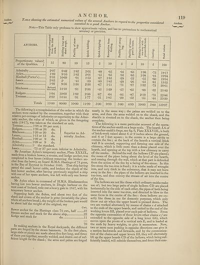
Note. This Table only prefessea lo W-toate^alue,. aad haS „„ pretensions to ntatboMatica!
ANCHORS.
Pa 2
S «
■& g u
Proportionate values)
of’the Qualities. j
Admiralty
Aylen
Honiball (Porter’s).
Isaacs
Lenox
Mitcheson,
Rodgers.
Trotman.
Totals
15
c Oh
80
10
2-07
1- 89
2- 33
2-63
1-92
Refused
this trial.
1- 94
2- 22
6-42
9-10
10-69
5-
9-56
14-10
10-69
14-44
1-82
1-82
•91
•45
1-36
•91
1-82
•91
o’
15
15-00
80-00
10-00
2-01
2-01
1- 53
•59
2- 36
2-36
2-36
1-77
o'
P< o
S^
10
14-99
•89
•45
•67
•89
•67
•45
•67
•31
5-00
•65
•65
1-85
1-85
Ml
1-39
•64
1-85
9-99
•95
•95
•29
•29
•71
•57
•95
•29
^ .e S
pC ."S rC
03 £ A
.2
bp £ C
P I 0)
ie m £
10
*65
•65
•52
•26
•87
•65
•87
•52
5-00 4-99
1-98
1-98
•55
•55
1*32
•88
2*19
•55
10-00
•73
•44
•60
•81
•73
•52
•73
•44
160
5-00
The following is a recapitulation of the order in which the
anchors were ranked by the committee, together with their
relative per-centage of inferiority or superiority to the Admi¬
ralty anchor, the value of which, as given in the foregoing
table (18-17), was taken as the standard or unit.
Trotman 1*28 or 28 per cent.
18- 17
19- 94
19- 94
13-32
20- 61
21- 83
22- 86
23-30
159-97
Superior to Ad¬
miralty Anchor.
Rodgers 1-26 or 26 ’ do.
Mitcheson 1-20 or 20 do.
Lenox M3 or 13 do.
Honiball P09 or 9 do.
Aylen 1-09 or 9 do. I
Admiralty 1- the standard.
^s^cs "73 or 27 per cent, inferior to Admiralty.
Mr Jonathan Aylen’s temporary anchor, Plate XXXIX.,
made from a broken bower, a stream, and kedge anchor, was
completed in four hours (without removing the broken an¬
chor from the bows), on board H.M.S. Hastings of 74 guns,
in the Bay of Beyrout in October 1840. That ship having
parted the small bower cable, and broken the shank of the
best bower anchor, after having previously supplied a ship
with one of her spare anchors, was left with only one bower
anchor.
Mr Aylen when in command of H.M.S. Rhadamanthus
avmg lost two bower anchors, in Dingle harbour on the
west coast of Ireland, rode out a heavy gale in 1847, with his
temporary bower anchor.
Supposing both the flukes, and about two feet of the
s lank and crown of the anchor is gone (invariably the place
w icre all anchors break), the weight of the broken part would
be about half the weight of the original, say
Cwt.
Bower anchor for the Hastings class 74 cwt., half 37
Stream anchor and stock for the above ship, 22
Kedge and stock for do. .) 11
In making anchors in the Royal dockyards, the different
parts are forged by the steam hammers. In the first place,
aige slabs or pieces are made about five feet long, and three
o em put together, soundly welded, and drawn out of suf-
cien ength for the shank; the arms and palms are forged
nearly in the same way; the palms are welded on to the
arms, and then the arms welded on to the shank, and the
shackle is rivetted on to the shank, the anchor then beino-
complete.
The following is a more particular account of the opera¬
tions of the anchor-smith on a large scale. The hearth A A of
the anchor-smith’s forge, see fig. 6, Plate XXXVIIL, is built
of brick-work raised about 6 or 9 inches above the ground,
and 6 or 7 feet square; in the centre is a large cavity to
contain the fire; at the back of the hearth a vertical brick
wall B is erected, supporting and forming one side of the
chimney, which is little more than a dome placed over the
hearth, and opening at the top with a low chimney to carry
off the smoke. Behind the wall the bellows CD are placed;
the noses of the pipes being about the level of the hearth,
and coming through the wall, which at that part is defended
from the action of the fire by a facing of fire-stone. In this
fire-stone the tue-iron is fixed; it is a tube made of wrought
iron, and very thick in the substance, that it may not burn
away in the fire: the pipes of the bellowrs are inserted in the
tue-iron, and thus convey the stream of air into the centre
of the fire.
The bellows are not like those which ordinary smiths make
use of; but two large pairs of single bellows CD are placed
horizontally by the side of each other, the pipes of both being
inserted into the same tue-iron, and directed to blow to the
same focus in the centre of the fire: these bellows are ex¬
actly like those in use for domestic purposes, which only
throw out air when the upper board is pressed down. The
two are worked alternately by means of chains c d attached
to the ends of the upper boards, and united to the end of the
working levers HI, placed over each pair of bellows. From
the opposite extremities of these levers other chains ef are
extended to the opposite side of a long lever GG, which
moves upon the pivots of a vertical axis E, and is loaded at
the ends by heavy weights, to give it momentum. Now,
two or more men pushing in opposite directions can give it
a motion backwards and forwards, and by the communica¬
tion of the chains and upper levers HI, they will alternately
lift up the upper boards CD of the bellows, which being suf¬
ficiently loaded, will subside themselves, and force their con-
ANCHOR.
Note. This Table only prefessea lo W-toate^alue,. aad haS „„ pretensions to ntatboMatica!
ANCHORS.
Pa 2
S «
■& g u
Proportionate values)
of’the Qualities. j
Admiralty
Aylen
Honiball (Porter’s).
Isaacs
Lenox
Mitcheson,
Rodgers.
Trotman.
Totals
15
c Oh
80
10
2-07
1- 89
2- 33
2-63
1-92
Refused
this trial.
1- 94
2- 22
6-42
9-10
10-69
5-
9-56
14-10
10-69
14-44
1-82
1-82
•91
•45
1-36
•91
1-82
•91
o’
15
15-00
80-00
10-00
2-01
2-01
1- 53
•59
2- 36
2-36
2-36
1-77
o'
P< o
S^
10
14-99
•89
•45
•67
•89
•67
•45
•67
•31
5-00
•65
•65
1-85
1-85
Ml
1-39
•64
1-85
9-99
•95
•95
•29
•29
•71
•57
•95
•29
^ .e S
pC ."S rC
03 £ A
.2
bp £ C
P I 0)
ie m £
10
*65
•65
•52
•26
•87
•65
•87
•52
5-00 4-99
1-98
1-98
•55
•55
1*32
•88
2*19
•55
10-00
•73
•44
•60
•81
•73
•52
•73
•44
160
5-00
The following is a recapitulation of the order in which the
anchors were ranked by the committee, together with their
relative per-centage of inferiority or superiority to the Admi¬
ralty anchor, the value of which, as given in the foregoing
table (18-17), was taken as the standard or unit.
Trotman 1*28 or 28 per cent.
18- 17
19- 94
19- 94
13-32
20- 61
21- 83
22- 86
23-30
159-97
Superior to Ad¬
miralty Anchor.
Rodgers 1-26 or 26 ’ do.
Mitcheson 1-20 or 20 do.
Lenox M3 or 13 do.
Honiball P09 or 9 do.
Aylen 1-09 or 9 do. I
Admiralty 1- the standard.
^s^cs "73 or 27 per cent, inferior to Admiralty.
Mr Jonathan Aylen’s temporary anchor, Plate XXXIX.,
made from a broken bower, a stream, and kedge anchor, was
completed in four hours (without removing the broken an¬
chor from the bows), on board H.M.S. Hastings of 74 guns,
in the Bay of Beyrout in October 1840. That ship having
parted the small bower cable, and broken the shank of the
best bower anchor, after having previously supplied a ship
with one of her spare anchors, was left with only one bower
anchor.
Mr Aylen when in command of H.M.S. Rhadamanthus
avmg lost two bower anchors, in Dingle harbour on the
west coast of Ireland, rode out a heavy gale in 1847, with his
temporary bower anchor.
Supposing both the flukes, and about two feet of the
s lank and crown of the anchor is gone (invariably the place
w icre all anchors break), the weight of the broken part would
be about half the weight of the original, say
Cwt.
Bower anchor for the Hastings class 74 cwt., half 37
Stream anchor and stock for the above ship, 22
Kedge and stock for do. .) 11
In making anchors in the Royal dockyards, the different
parts are forged by the steam hammers. In the first place,
aige slabs or pieces are made about five feet long, and three
o em put together, soundly welded, and drawn out of suf-
cien ength for the shank; the arms and palms are forged
nearly in the same way; the palms are welded on to the
arms, and then the arms welded on to the shank, and the
shackle is rivetted on to the shank, the anchor then beino-
complete.
The following is a more particular account of the opera¬
tions of the anchor-smith on a large scale. The hearth A A of
the anchor-smith’s forge, see fig. 6, Plate XXXVIIL, is built
of brick-work raised about 6 or 9 inches above the ground,
and 6 or 7 feet square; in the centre is a large cavity to
contain the fire; at the back of the hearth a vertical brick
wall B is erected, supporting and forming one side of the
chimney, which is little more than a dome placed over the
hearth, and opening at the top with a low chimney to carry
off the smoke. Behind the wall the bellows CD are placed;
the noses of the pipes being about the level of the hearth,
and coming through the wall, which at that part is defended
from the action of the fire by a facing of fire-stone. In this
fire-stone the tue-iron is fixed; it is a tube made of wrought
iron, and very thick in the substance, that it may not burn
away in the fire: the pipes of the bellowrs are inserted in the
tue-iron, and thus convey the stream of air into the centre
of the fire.
The bellows are not like those which ordinary smiths make
use of; but two large pairs of single bellows CD are placed
horizontally by the side of each other, the pipes of both being
inserted into the same tue-iron, and directed to blow to the
same focus in the centre of the fire: these bellows are ex¬
actly like those in use for domestic purposes, which only
throw out air when the upper board is pressed down. The
two are worked alternately by means of chains c d attached
to the ends of the upper boards, and united to the end of the
working levers HI, placed over each pair of bellows. From
the opposite extremities of these levers other chains ef are
extended to the opposite side of a long lever GG, which
moves upon the pivots of a vertical axis E, and is loaded at
the ends by heavy weights, to give it momentum. Now,
two or more men pushing in opposite directions can give it
a motion backwards and forwards, and by the communica¬
tion of the chains and upper levers HI, they will alternately
lift up the upper boards CD of the bellows, which being suf¬
ficiently loaded, will subside themselves, and force their con-
Set display mode to:
![]() Universal Viewer |
Universal Viewer | ![]() Mirador |
Large image | Transcription
Mirador |
Large image | Transcription
Images and transcriptions on this page, including medium image downloads, may be used under the Creative Commons Attribution 4.0 International Licence unless otherwise stated. ![]()
| Encyclopaedia Britannica > Encyclopaedia Britannica > Volume 3, Anatomy-Astronomy > (127) Page 119 |
|---|
| Permanent URL | https://digital.nls.uk/193758999 |
|---|
| Attribution and copyright: |
|
|---|---|
| Shelfmark | EB.16 |
|---|---|
| Description | Ten editions of 'Encyclopaedia Britannica', issued from 1768-1903, in 231 volumes. Originally issued in 100 weekly parts (3 volumes) between 1768 and 1771 by publishers: Colin Macfarquhar and Andrew Bell (Edinburgh); editor: William Smellie: engraver: Andrew Bell. Expanded editions in the 19th century featured more volumes and contributions from leading experts in their fields. Managed and published in Edinburgh up to the 9th edition (25 volumes, from 1875-1889); the 10th edition (1902-1903) re-issued the 9th edition, with 11 supplementary volumes. |
|---|---|
| Additional NLS resources: |
|