Encyclopaedia Britannica > Volume 3, Anatomy-Astronomy
(126) Page 118
Download files
Complete book:
Individual page:
Thumbnail gallery: Grid view | List view
118
ANCHOR.
Anchor. Besides anchors of the common construction, there are
various others of different forms occasionally in use. Small
vessels often employ what are termed grapnels, which are
merely common anchors with four or more arms instead of
two, as shown in fig. 6. Following out the same principle,
we have the mushroom anchor, fig. 7, much employed in
the East Indies, to secure the vessels which they term grabs.
In this the arms are continued in one segment of a sphere
all round; it hence requires no stock, as it takes the ground
in any direction. Attempts have frequently been made to
introduce anchors with only one arm, but hitherto without
any decisive result. A patent for an anchor of this kind, as
represented at Plate XXXIX. fig. 8, was taken out by Mr
Stuard, which has attracted some notice. “ In order,” says
he, in the specification of his patent, “that this anchor may be
sure to fall the right way with the fluke downwards, I would
have the shank very short, whereby, when suspended by
the cable, it will cant the most, and when it has hold in the
ground, the ship will ride safer; as a long shank has more
power to loosen and break the ground, and is more likely to
be bent or broken from its hold. Let the form of the shank
and arm of the anchor be as A A, fig. 8 ; and, that the parts
may be stronger than if made separately and shut together,
I would have the bars which compose them in one length,
so that there be no weld or joining in the whole length of
the shank and arm. The hole B is to receive the ring for
the cable, and the hole C is for the stock, which is composed
of a wrought-iron bolt, as A, fig. 8, covered with cast-iron
at its ends, BB. The palm to be in shape as D, fig. 8, made
either entirely of cast-iron, or cast-iron shell filled with lead,
which is of much more specific gravity than iron. The back
of the palm to be formed either with concave surfaces or flat
surfaces, making angles at the centre. The anchor is also
to have a small shackle, fixed on the bend of the shank and
arm, as at E, fig. 8, for the buoy-rope to be made fast to.
The shank may be made without the hole C, and the hole
B made octagonal; or if round, it should have a small fillet
projecting from the stock, and a small cavity on one side
of the hole B to receive it, thus to prevent the stock from
turning round; and instead of a ring for the cable, to have
a shackle fitted on the stock, on each side of the shank; and,
that the shackle may not turn on the stock and fall too low,
a stop is to be fixed on each side at the upper end of the
shank.”—See Repertory of Arts, &c., vol. v.
New moor- Mooring Anchors are those which are fixed in certain
ing anchor, situations in harbours or roadsteads, and to which any of
the vessels frequenting the place may be secured. As these
are no way limited as to weight like portable anchors, they
often consist merely of a large block of stone, such as at
fig. 9, with an inner ring fixed in the middle of the upper
side ; or several such stones may be fastened together so as
to act as one mass. Mooring anchors are also often made by
choosing one of the largest anchors used for first-rate ships,
weighing 80 cwt., and by bending one of the arms close
down upon the shank, to prevent it catching hawsers when
transporting ships, nets of fishermen, fouling, &c. These an¬
chors are lowered down into the water with a very strono- iron
mooring chain fastened to the ring, to which the ships are
fastened. they are usually made from such as are damaged
in one of the flukes or arms. A new kind of mooring anchor
of cast-iron was described by Mr Hemman of Chatham, to
the Society for the Encouragement of Arts, fyc., in 1809
for which he obtained a silver medal from the society. Fig!
5, Plate XXXIX., represents the palm or heavy part of the
anchor, made very massive of cast-iron, and of considerable
breadth, so that the edge B, or part which enters the ground,
may have a great hold; the shank C is made also of cast-
iron, and fixed firmly to the head bypassing through it, and
has a small ring at a, where the buoy-rope is fixed; the other
end of the shank goes through the stock dd, which is formed Anchor
of two large wooden beams hooped together in the same
manner as the stocks for common anchors ; the end of the
shank projects through the stock, and has a strong wrought-
iron shackle E fixed to it by a bolt passing through both,
and with this the mooring chain is connected. The great
advantage of this over the common mooring anchors arises
from its great weight and breadth of edge to act against the
ground, and being made of cast-iron. A pair of these anchors,
weighing 150 cwt. each, will, with the mooring chains, cost
about L.874 less than a pair of the common anchors, which
with their chains, cost L.2472.—See Transactions of the
Society for the Encouragement of Arts, fyc., vol. xxviii.
This is the name given to a sort of anchor which has often Floating,
been proposed, but never reduced to practice, for prevent- anchor.0
ing a vessel from drifting, in cases where the great depth of
the sea precludes the use of the cable and ordinary anchor.
The plan suggested by Dr Franklin seems the most rational.
This anchor consisted of two cross bars, secured together
in the middle, and having sailcloth fastened to them in the
shape of a parallelogram. To the centre of these bars the
cable was attached, and being thrown overboard, it was
thought the resistance of so large a surface would at least
check the rapidity of the ship’s motion.
The following is Mr Aylen’s plan for anchoring in deep
water out of soundings, to prevent vessels from drifting in a
calm when in a tide-way, or if disabled :—Hoist out imme¬
diately one of the boom-boats, let go the kedge anchor, and
veer out 40 or 50 fms. over the bow, and stop it to the ring
in the bow and stern of the boat, then veer out from the ship
from 70 to 80 fms.
Much attention has been paid of late to the improvement
of the manufacture of anchors, and several specimens were
sent by the makers to the Royal Exhibition in 1851.
A committee, consisting of five shipowners of London,
Liverpool, and Glasgow, with five nominated by the Lords
of the Admiralty, was appointed to test the relative merits
of these. After trying, on the parade ground of Sheerness
dockyard, on the beach at Garrison point, at Biackstakes in
the River Medway, and at the Nore, those that were sub¬
mitted for competition, viz., Admiralty, Aylen’s (a modi¬
fied Admiralty), Honiball (or Porter’s), Isaacs’ (United
States), Lenox’s, Mitcheson’s, Rodgers’, and Trotman’s (an
improved Porter’s), they reported in 1853 that, taking into
consideration the results of all the trials to which the an¬
chors had been subjected, they thought it best to record
their opinions in the following tabulated forms :—
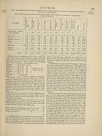
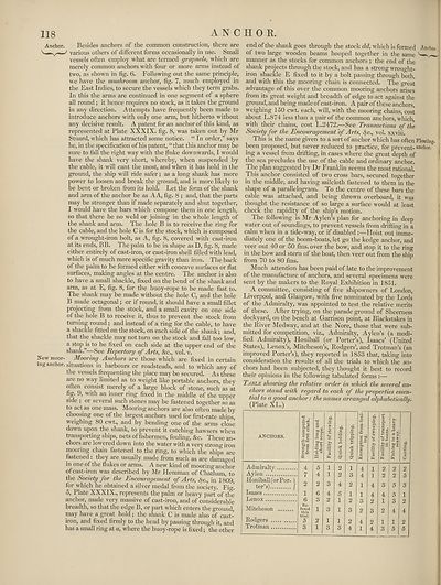
Table showing the relative order in which the several an¬
chors stand with regard to each of the properties essen¬
tial to a good anchor: the names arranged alphabeticalh/.
(Plate XL.)
ANCHORS.
Admiralty
Aylen
Honiball (or Por- (
ter’s) /
Isaacs
Lenox
Mitcheson
Rodgers
Trotman
s «
bed
1
6
Re-
fused
this
trial.
5
11
ANCHOR.
Anchor. Besides anchors of the common construction, there are
various others of different forms occasionally in use. Small
vessels often employ what are termed grapnels, which are
merely common anchors with four or more arms instead of
two, as shown in fig. 6. Following out the same principle,
we have the mushroom anchor, fig. 7, much employed in
the East Indies, to secure the vessels which they term grabs.
In this the arms are continued in one segment of a sphere
all round; it hence requires no stock, as it takes the ground
in any direction. Attempts have frequently been made to
introduce anchors with only one arm, but hitherto without
any decisive result. A patent for an anchor of this kind, as
represented at Plate XXXIX. fig. 8, was taken out by Mr
Stuard, which has attracted some notice. “ In order,” says
he, in the specification of his patent, “that this anchor may be
sure to fall the right way with the fluke downwards, I would
have the shank very short, whereby, when suspended by
the cable, it will cant the most, and when it has hold in the
ground, the ship will ride safer; as a long shank has more
power to loosen and break the ground, and is more likely to
be bent or broken from its hold. Let the form of the shank
and arm of the anchor be as A A, fig. 8 ; and, that the parts
may be stronger than if made separately and shut together,
I would have the bars which compose them in one length,
so that there be no weld or joining in the whole length of
the shank and arm. The hole B is to receive the ring for
the cable, and the hole C is for the stock, which is composed
of a wrought-iron bolt, as A, fig. 8, covered with cast-iron
at its ends, BB. The palm to be in shape as D, fig. 8, made
either entirely of cast-iron, or cast-iron shell filled with lead,
which is of much more specific gravity than iron. The back
of the palm to be formed either with concave surfaces or flat
surfaces, making angles at the centre. The anchor is also
to have a small shackle, fixed on the bend of the shank and
arm, as at E, fig. 8, for the buoy-rope to be made fast to.
The shank may be made without the hole C, and the hole
B made octagonal; or if round, it should have a small fillet
projecting from the stock, and a small cavity on one side
of the hole B to receive it, thus to prevent the stock from
turning round; and instead of a ring for the cable, to have
a shackle fitted on the stock, on each side of the shank; and,
that the shackle may not turn on the stock and fall too low,
a stop is to be fixed on each side at the upper end of the
shank.”—See Repertory of Arts, &c., vol. v.
New moor- Mooring Anchors are those which are fixed in certain
ing anchor, situations in harbours or roadsteads, and to which any of
the vessels frequenting the place may be secured. As these
are no way limited as to weight like portable anchors, they
often consist merely of a large block of stone, such as at
fig. 9, with an inner ring fixed in the middle of the upper
side ; or several such stones may be fastened together so as
to act as one mass. Mooring anchors are also often made by
choosing one of the largest anchors used for first-rate ships,
weighing 80 cwt., and by bending one of the arms close
down upon the shank, to prevent it catching hawsers when
transporting ships, nets of fishermen, fouling, &c. These an¬
chors are lowered down into the water with a very strono- iron
mooring chain fastened to the ring, to which the ships are
fastened. they are usually made from such as are damaged
in one of the flukes or arms. A new kind of mooring anchor
of cast-iron was described by Mr Hemman of Chatham, to
the Society for the Encouragement of Arts, fyc., in 1809
for which he obtained a silver medal from the society. Fig!
5, Plate XXXIX., represents the palm or heavy part of the
anchor, made very massive of cast-iron, and of considerable
breadth, so that the edge B, or part which enters the ground,
may have a great hold; the shank C is made also of cast-
iron, and fixed firmly to the head bypassing through it, and
has a small ring at a, where the buoy-rope is fixed; the other
end of the shank goes through the stock dd, which is formed Anchor
of two large wooden beams hooped together in the same
manner as the stocks for common anchors ; the end of the
shank projects through the stock, and has a strong wrought-
iron shackle E fixed to it by a bolt passing through both,
and with this the mooring chain is connected. The great
advantage of this over the common mooring anchors arises
from its great weight and breadth of edge to act against the
ground, and being made of cast-iron. A pair of these anchors,
weighing 150 cwt. each, will, with the mooring chains, cost
about L.874 less than a pair of the common anchors, which
with their chains, cost L.2472.—See Transactions of the
Society for the Encouragement of Arts, fyc., vol. xxviii.
This is the name given to a sort of anchor which has often Floating,
been proposed, but never reduced to practice, for prevent- anchor.0
ing a vessel from drifting, in cases where the great depth of
the sea precludes the use of the cable and ordinary anchor.
The plan suggested by Dr Franklin seems the most rational.
This anchor consisted of two cross bars, secured together
in the middle, and having sailcloth fastened to them in the
shape of a parallelogram. To the centre of these bars the
cable was attached, and being thrown overboard, it was
thought the resistance of so large a surface would at least
check the rapidity of the ship’s motion.
The following is Mr Aylen’s plan for anchoring in deep
water out of soundings, to prevent vessels from drifting in a
calm when in a tide-way, or if disabled :—Hoist out imme¬
diately one of the boom-boats, let go the kedge anchor, and
veer out 40 or 50 fms. over the bow, and stop it to the ring
in the bow and stern of the boat, then veer out from the ship
from 70 to 80 fms.
Much attention has been paid of late to the improvement
of the manufacture of anchors, and several specimens were
sent by the makers to the Royal Exhibition in 1851.
A committee, consisting of five shipowners of London,
Liverpool, and Glasgow, with five nominated by the Lords
of the Admiralty, was appointed to test the relative merits
of these. After trying, on the parade ground of Sheerness
dockyard, on the beach at Garrison point, at Biackstakes in
the River Medway, and at the Nore, those that were sub¬
mitted for competition, viz., Admiralty, Aylen’s (a modi¬
fied Admiralty), Honiball (or Porter’s), Isaacs’ (United
States), Lenox’s, Mitcheson’s, Rodgers’, and Trotman’s (an
improved Porter’s), they reported in 1853 that, taking into
consideration the results of all the trials to which the an¬
chors had been subjected, they thought it best to record
their opinions in the following tabulated forms :—
Table showing the relative order in which the several an¬
chors stand with regard to each of the properties essen¬
tial to a good anchor: the names arranged alphabeticalh/.
(Plate XL.)
ANCHORS.
Admiralty
Aylen
Honiball (or Por- (
ter’s) /
Isaacs
Lenox
Mitcheson
Rodgers
Trotman
s «
bed
1
6
Re-
fused
this
trial.
5
11
Set display mode to:
![]() Universal Viewer |
Universal Viewer | ![]() Mirador |
Large image | Transcription
Mirador |
Large image | Transcription
Images and transcriptions on this page, including medium image downloads, may be used under the Creative Commons Attribution 4.0 International Licence unless otherwise stated. ![]()
| Encyclopaedia Britannica > Encyclopaedia Britannica > Volume 3, Anatomy-Astronomy > (126) Page 118 |
|---|
| Permanent URL | https://digital.nls.uk/193758986 |
|---|
| Attribution and copyright: |
|
|---|---|
| Shelfmark | EB.16 |
|---|---|
| Description | Ten editions of 'Encyclopaedia Britannica', issued from 1768-1903, in 231 volumes. Originally issued in 100 weekly parts (3 volumes) between 1768 and 1771 by publishers: Colin Macfarquhar and Andrew Bell (Edinburgh); editor: William Smellie: engraver: Andrew Bell. Expanded editions in the 19th century featured more volumes and contributions from leading experts in their fields. Managed and published in Edinburgh up to the 9th edition (25 volumes, from 1875-1889); the 10th edition (1902-1903) re-issued the 9th edition, with 11 supplementary volumes. |
|---|---|
| Additional NLS resources: |
|