Robert Watson-Watt (1892-1973)
An instantaneous direct-reading radiogoniometer
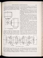
DIRECT-READING RADIOGONIOMETER.
613
are connected to the central earth lead, whilst the grids
are each connected to the high-potential sides of the
tuning condensers in the half-loops. The oscillograph
deflecting plates are joined through coupling condensers
to points on the high resistances included in the plate
circuits.
[NLS note: a graphic appears here – see image of page]
FIG. 2.– General arrangement of cathode-ray
direction-finder.
In the actual installation under description, the loops
are supported on a mast system comprising a central
wood lattice mast 200 ft. high, and four wood box
masts 150 ft. high, at the corners of a square of 1 200 ft.
diagonal. Each loop comprises five turns, which can
be grouped in series or parallel, each turn measuring
1200 ft. horizontally by some 150 ft. deep, the area-
turns in the series grouping being thus about
8·4 × 104 m2 (about 20 acres). The inductance of
the series arrangement is 19 mH, and the effective
resistance at 10 kilocycles is 200 ohms. Each unit of
the tuning system, as used for atmospheric observations
at about 10 kilocycles, comprises a coil of 136 mH and
an air and mica condenser assembly with a maximum
capacity of 0·006 µF. The arrangement of these units
will be referred to later.
[NLS note: a graphic appears here – see image of page]
FIG. 3.– Details of circuits.
The amplifiers are based on the use of the D.E. 5B
triode, and with anode resistances (wire wound) of
105 ohms, and plate circuit voltage 300, give a voltage
magnification of 15 per stage. The first anode resistance
in each side is tapped approximately in thirds, so that
the available voltage magnifications are 5, 10, 15, 75,
150 and 225.
The oscillograph has a deflectional sensitivity of 1 mm
per volt, so that the sensitivities of the combination of
amplifier and oscillograph are 1 mm for 200, 100, 67,
13, 7, and 4 millivolts respectively on grid. Full-scale
deflection, reaching the outer edge of the oscillograph
screen, amounts to 50 mm, the angular scale value then
being 0·87 mm per degree of angle. So far as reading
goes, therefore, accuracies of 1° can be attained en any
deflection exceeding half scale.
The two special features of this installation are the
precautions taken to ensure symmetry, and the large
areas of loop used. This latter feature is part of a
general policy which has guided all our quantitative
work on atmospherics, namely that the antenna system
should be of such dimensions as to allow measurements
to be made with a minimum of amplification. It is
a general experience that quantitative uncertainties
increase rapidly as amplification is increased, and for
fundamental work the more antenna and the less
amplifier the better. It must not be thought, however,
that acres of antennæ are essential to the system, nor
that the somewhat uneconomical duplication of triodes,
giving only a doubling of amplification, in the push-pull
system is inevitable. The use of loops the indi-
vidual turns of which have an area of 30 m2, with
one pair of vertical sides coincident, in combination with
normal amplifiers and the standard form of cathode-ray
oscillograph, has already been shown to be practicable,
and further wide modifications should result from syste-
matic development work, which has not been required
for work on atmospherics but is desirable for the
production of a compact visual direction-finder for
general use.
The principal conditions to be fulfilled by the system
- © National Library of Scotland 2009
- NLS home page
- Digital library