
Medicine - Veterinary > Veterinary colleges and laboratories > Indian journal of veterinary science and animal husbandry > Volume 12, 1942 > Original articles > Cheap and accurate home-made automatic pipette
(59) Page 51
Download files
Individual page:
Thumbnail gallery: Grid view | List view
JOHN B. POLDING 51
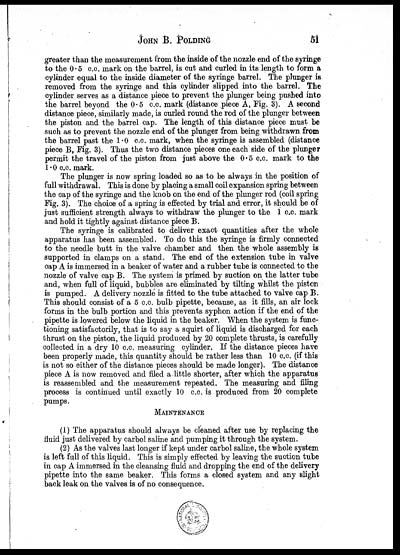
greater than the measurement from the inside of the nozzle end of the syringe
to the 0.5 c.c. mark on the barrel, is cut and curled in its length to form a
cylinder equal to the inside diameter of the syringe barrel. The plunger is
removed from the syringe and this cylinder slipped into the barrel. The
cylinder serves as a distance piece to prevent the plunger being pushed into
the barrel beyond the 0.5 c.c. mark (distance piece A, Fig. 3). A second
distance piece, similarly made, is curled round the rod of the plunger between
the piston and the barrel cap. The length of this distance piece must be
such as to prevent the nozzle end of the plunger from being withdrawn from
the barrel past the 1.0 c.c. mark, when the syringe is assembled (distance
piece B, Fig. 3). Thus the two distance pieces one each side of the plunger
permit the travel of the piston from just above the 0.5 c.c. mark to the
1.0 c.c. mark.
The plunger is now spring loaded so as to be always in the position of
full withdrawal. This is done by placing a small coil expansion spring between
the cap of the syringe and the knob on the end of the plunger rod (coil spring
Fig. 3). The choice of a spring is effected by trial and error, it should be of
just sufficient strength always to withdraw the plunger to the 1 c.c. mark
and hold it tightly against distance piece B.
The syringe is calibrated to deliver exact quantities after the whole
apparatus has been assembled. To do this the syringe is firmly connected
to the needle butt in the valve chamber and then the whole assembly is
supported in clamps on a stand. The end of the extension tube in valve
cap A is immersed in a beaker of water and a rubber tube is connected to the
nozzle of valve cap B. The system is primed by suction on the latter tube
and, when full of liquid, bubbles are eliminated by tilting whilst the piston
is pumped. A delivery nozzle is fitted to the tube attached to valve cap B.
This should consist of a 5 c.c. bulb pipette, because, as it fills, an air lock
forms in the bulb portion and this prevents syphon action if the end of the
pipette is lowered below the liquid in the beaker. When the system is func-
tioning satisfactorily, that is to say a squirt of liquid is discharged for each
thrust on the piston, the liquid produced by 20 complete thrusts, is carefully
collected in a dry 10 c.c. measuring cylinder. If the distance pieces have
been properly made, this quantity should be rather less than 10 c.c. (if this
is not so either of the distance pieces should be made longer). The distance
piece A is now removed and filed a little shorter, after which the apparatus
is reassembled and the measurement repeated. The measuring and filing
process is continued until exactly 10 c.c. is produced from 20 complete
pumps.
MAINTENANCE
(1) The apparatus should always be cleaned after use by replacing the
fluid just delivered by carbol saline and pumping it through the system.
(2) As the valves last longer if kept under carbol saline, the whole system
is left full of this liquid. This is simply effected by leaving the suction tube
in cap A immersed in the cleansing fluid and dropping the end of the delivery
pipette into the same beaker. This forms a closed system and any slight
back leak on the valves is of no consequence.
Set display mode to: Large image | Zoom image | Transcription
Images and transcriptions on this page, including medium image downloads, may be used under the Creative Commons Attribution 4.0 International Licence unless otherwise stated. ![]()
| Permanent URL | https://digital.nls.uk/75259262 |
|---|
| Description | Covers articles from 1942. |
|---|
| Description | Volumes 1-29 cover a wide range of topics related to veterinary science and animal husbandry. Black and white and colour plates accompany some articles. Each volume covers one year and has indexes to both authors and subjects at the end. Reviews, obituaries and abstracts are also included. |
|---|---|
| Shelfmark | IP/RA.11 |
| Additional NLS resources: | |
| Attribution and copyright: |
|
| Description | Reports from veterinary colleges and annual reports of the Imperial Bacteriologist. Plus volumes of the Indian Journal of Veterinary Science and Animal Husbandry covering 1931-1959. |
|---|---|
| Shelfmark | India Papers |
| Description | The Veterinary collection consists of 146 volumes dating from 1864 to 1959. Divided into veterinary diseases, colleges and laboratories and Civil Veterinary Departments. Extensive research on trypanosomiasis and rinderpest. Reports show how veterinary medicine controlled disease, maintained livestock and alleviated famine. They explore its effect on military and local communities. |
|---|---|
| Shelfmark | India Papers |
| Description | The India Papers collection contains publications of the central (Imperial) Government and many Indian states. Most states came under British rule. Much of the collection dates from between the post-Mutiny re-organisation of the Indian Government and Indian Independence in 1947. Some items published in London by John Murray. |
|---|---|
| Shelfmark | India Papers |
| Additional NLS resources: | |