Encyclopaedia Britannica > Volume 21, ROT-Siam
(828) Page 818
Download files
Complete book:
Individual page:
Thumbnail gallery: Grid view | List view
818
S H I P B U
I L D I N G
Curves of
strains.
H.M.S.
‘4 Mino¬
taur.”
upperworks, and their power to resist a tensile strain. There is
seldom a want of sufficient strength in the lower parts of the
vessel to resist the crushing or compressing force to which it is
subjected. The decks of vessels should not, therefore, he too much
cut up by broad hatchways ; and care should be taken to preserve
entire as many strakes of the deck as possible. The tensile strength
of iron can be brought to hear most beneficially in this respect.
Though these are the strains to which a ship is most likely to
be exposed, it by no means follows that there are no circumstances
under which strains of the directly opposite tendency, when pitch¬
ing, or otherwise, may be brought by recoil to act upon the parts.
The weights themselves in the centre of the ship may be so great
that they may have a tendency to give a hollow curvature to the
form, and it is therefore equally necessary to guard against this
evil. When this occurs, the vessel is technically said to be
“ sagged, ” in distinction to the contrary or opposite change of
form by being hogged. The weight of machinery in a wooden
steam-vessel, or the weight or undue setting up of the main-mast,
will sometimes produce sagging. The introduction of additional
keelsons tended to lessen this evil, by giving great additional
strength to the bottom, enabling it to resist extension, to which,
under such circumstances, it became liable ; and, as the strain upon
the deck and upperworks becomes changed at the same time, they
are then called upon to resist compression.
When the ship is on a wind, the lee-side is subjected to a series
of shocks from the waves, the violence of which may he imagined
from the effects they sometimes produce in destroying the bul¬
warks, tearing away the channels, &c. The lee-side is also sub¬
jected to an excess of hydrostatic pressure over that upon the
weather side, resulting from the accumulation of the waves as they
rise against the obstruction offered to their free passage. These
forces tend in part to produce lateral curvature. When in this
inclined position, the forces which tend to produce hogging when
she is upright also contribute to produce this lateral curvature.
The strain from the tension of the rigging on the weather side
when the ship is much inclined is so great as frequently to cause
working in the topsides, and sometimes even to break the timbers
on which the channels are placed. Additional strength ought
therefore to be given to the sides of the ship at this place ; and, in
order to keep them apart, the beams ought to be increased in
strength in comparison with the beams at other parts of the ship.
The foregoing are the principal disturbing forces to which the
fabric of a ship is subjected ; and it must be borne in mind that
some of these are in almost constant activity to destroy the con¬
nexion between the several parts. Whenever any motion or
working is produced by their operation between two parts, which
ought to be united in a fixed or firm manner, the evil will soon
increase, because the disruption of the close connexion between
these parts admits an increased momentum in their action on
each other, and the destruction proceeds with an accelerated pro¬
gression. This is soon followed by the admission of damp, and
the unavoidable accumulation of dirt, and these then generate
fermentation and decay. To make a ship strong, therefore, is at
the same time to make her durable, both in reference to the wear
and tear of service and the decay of materials. It is evident from
the foregoing remarks that the disturbing influences which cause
‘ ‘ hogging ” are in constant operation from the moment of launch¬
ing the ship. As this curvature can only take place by the com¬
pression of the materials composing the lower parts of the ship and
the extension of those composing the upper parts, the importance
of preparing these separate parts with an especial view to withstand
the forces to which they are each to be subjected cannot be over¬
rated by the practical builder.
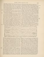
In his Manual of Naval Architecture, Mr W. H. White gives illus¬
trations of the
still-water strains
upon two ar¬
moured ships in
the British navy
the ‘ ‘ Minotaur ”
and the “Devas¬
tation.”
In these diagrams the curves B represent the distribution of the
buoyancy. The ordinates of the curve are proportionate to the
displacement of ad- M
jacent transverse
sections of the
ships. The curves
W represent the
distribution of the
weight of the ships
and their lading.
The curves L repre¬
sent the excesses
and defects of buoy- 10
ancy obtained from
the two curves B and W and set off from a new base line. The
Fig. 9-
excess of buoyancy above the line is exactly equal to the defect of
buoyancy below it. The curves M indicate the bending moments.
The ordinates of the curve lying above the base are obtained
by summing all the moments,
whether upwards or downwards,
about the point in the length of
the ship where the ordinate is
taken. It may happen, as in
the case of the “ Devastation, ”
that the moments will tend to
cause hogging for a portion of
the length and will then change
their character, and at other por¬
tions of the length will tend to
cause sagging. Where the curve M crosses the base line there is
no strain of either hogging or sagging tending to bend the ship
there. In the ‘ ‘ Minotaur ”
there is a hogging tendency
throughout. The amount at e
the midship section is very
great, being represented by
the moment 4 -5 feet x 10 '690
tons. After Sir Edward Reed
left the Admiralty he strongly
expressed his fears that this
strain was too considerable for safety in the “Minotaur” and
“ Agincourt.”
Designing.
The principal plans of a ship are the “sheer’’plan, giving in
outline the longitudinal elevation of the ship; the “ body” plan,
giving the shape of the vertical transverse sections ; and the
“ half-breadth ” plan, giving the projections of transverse longi¬
tudinal sections. In addition to these the builder is furnished by
the designer with elevations, plans, and sections of the interior
parts of the ship, and of the framing and plating or planking.
The thicknesses or weights of all the component parts are specified
in a detailed specification, in order that the ship when completed
may have the precise weight and position of centre of gravity con¬
templated by the designer. In the case of ships built for the British
navy all the building materials are carefully weighed by an agent
of the designer before they are put into place by the builder. As
each section of the work is completed, the weight is compared with
the designer’s estimate in the designing office. As soon as the
incomplete hull is floated the actual displacement is measured, and
compared with the weights recorded as having gone into the ship.
It is also the practice in the Royal Navy to calculate the position
of the centre of gravity of the incomplete hull, and its draught of
water before it is floated, in order to avoid all risk of upsetting
from deficiency in stability at that stage of construction. The ship
is usually found to float in precise accordance with the estimate.
When completed ships float at a deeper draught than was intended,
or are found to be more or less stable than was wished, this is
nearly always due to additions and alterations made after the com¬
pletion of the design. Where the designer is at liberty to complete
the ship in accordance with the original intention there ought to
be precise correspondence between the design and the ship.
In designing a ship of novel type the designer has to pass all
the building details through his mind and assign them their just
weights and proportions and positions. Every plate and angle bar
and plank, every bar and rod and casting and forging, and every
article of equipment has to be conceived in detail and its effect
estimated.
Fig. 12.
H.M.S.
‘4 Devas¬
tation. ”
Building.
The term “laying off” is applied to the operation of transferring Laying
to the mould loft floor those designs and general proportions of a 0ff,
ship which have been drawn on paper, and from which all the
preliminary calculations have been made and the form decided.
The lines of the ship, and exact representations of many of the
parts of which it is to be composed, are to be delineated there to
their full size, or the actual or real dimensions, in order that
moulds or skeleton outlines may be made from them for the
guidance of the workmen.
A ship is generally spoken of as divided into fore and after Fore and
bodies, and these combined constitute the whole of the ship ; they after
are supposed to he separated by an imaginary athwartship section bodies,
at the widest part of the ship, called the midship section or dead-
fiat. The midship body is a term applied to an indefinite length of
the middle part of a ship longitudinally, including a portion of
the fore-body and of the after-body. It is not necessarily parallel
or of the same form for its whole length.
Those portions of a wooden ship which are termed the square
and cant bodies may be considered as subdivisions of the fore-bodies
and after-bodies. There is a square fore-body and a square after¬
body towards the middle of the ship, and a cant fore-body and a
cant after-body at the two ends. In the square body the sides of
the frames are square to the line of the keel, and are athwartship
S H I P B U
I L D I N G
Curves of
strains.
H.M.S.
‘4 Mino¬
taur.”
upperworks, and their power to resist a tensile strain. There is
seldom a want of sufficient strength in the lower parts of the
vessel to resist the crushing or compressing force to which it is
subjected. The decks of vessels should not, therefore, he too much
cut up by broad hatchways ; and care should be taken to preserve
entire as many strakes of the deck as possible. The tensile strength
of iron can be brought to hear most beneficially in this respect.
Though these are the strains to which a ship is most likely to
be exposed, it by no means follows that there are no circumstances
under which strains of the directly opposite tendency, when pitch¬
ing, or otherwise, may be brought by recoil to act upon the parts.
The weights themselves in the centre of the ship may be so great
that they may have a tendency to give a hollow curvature to the
form, and it is therefore equally necessary to guard against this
evil. When this occurs, the vessel is technically said to be
“ sagged, ” in distinction to the contrary or opposite change of
form by being hogged. The weight of machinery in a wooden
steam-vessel, or the weight or undue setting up of the main-mast,
will sometimes produce sagging. The introduction of additional
keelsons tended to lessen this evil, by giving great additional
strength to the bottom, enabling it to resist extension, to which,
under such circumstances, it became liable ; and, as the strain upon
the deck and upperworks becomes changed at the same time, they
are then called upon to resist compression.
When the ship is on a wind, the lee-side is subjected to a series
of shocks from the waves, the violence of which may he imagined
from the effects they sometimes produce in destroying the bul¬
warks, tearing away the channels, &c. The lee-side is also sub¬
jected to an excess of hydrostatic pressure over that upon the
weather side, resulting from the accumulation of the waves as they
rise against the obstruction offered to their free passage. These
forces tend in part to produce lateral curvature. When in this
inclined position, the forces which tend to produce hogging when
she is upright also contribute to produce this lateral curvature.
The strain from the tension of the rigging on the weather side
when the ship is much inclined is so great as frequently to cause
working in the topsides, and sometimes even to break the timbers
on which the channels are placed. Additional strength ought
therefore to be given to the sides of the ship at this place ; and, in
order to keep them apart, the beams ought to be increased in
strength in comparison with the beams at other parts of the ship.
The foregoing are the principal disturbing forces to which the
fabric of a ship is subjected ; and it must be borne in mind that
some of these are in almost constant activity to destroy the con¬
nexion between the several parts. Whenever any motion or
working is produced by their operation between two parts, which
ought to be united in a fixed or firm manner, the evil will soon
increase, because the disruption of the close connexion between
these parts admits an increased momentum in their action on
each other, and the destruction proceeds with an accelerated pro¬
gression. This is soon followed by the admission of damp, and
the unavoidable accumulation of dirt, and these then generate
fermentation and decay. To make a ship strong, therefore, is at
the same time to make her durable, both in reference to the wear
and tear of service and the decay of materials. It is evident from
the foregoing remarks that the disturbing influences which cause
‘ ‘ hogging ” are in constant operation from the moment of launch¬
ing the ship. As this curvature can only take place by the com¬
pression of the materials composing the lower parts of the ship and
the extension of those composing the upper parts, the importance
of preparing these separate parts with an especial view to withstand
the forces to which they are each to be subjected cannot be over¬
rated by the practical builder.
In his Manual of Naval Architecture, Mr W. H. White gives illus¬
trations of the
still-water strains
upon two ar¬
moured ships in
the British navy
the ‘ ‘ Minotaur ”
and the “Devas¬
tation.”
In these diagrams the curves B represent the distribution of the
buoyancy. The ordinates of the curve are proportionate to the
displacement of ad- M
jacent transverse
sections of the
ships. The curves
W represent the
distribution of the
weight of the ships
and their lading.
The curves L repre¬
sent the excesses
and defects of buoy- 10
ancy obtained from
the two curves B and W and set off from a new base line. The
Fig. 9-
excess of buoyancy above the line is exactly equal to the defect of
buoyancy below it. The curves M indicate the bending moments.
The ordinates of the curve lying above the base are obtained
by summing all the moments,
whether upwards or downwards,
about the point in the length of
the ship where the ordinate is
taken. It may happen, as in
the case of the “ Devastation, ”
that the moments will tend to
cause hogging for a portion of
the length and will then change
their character, and at other por¬
tions of the length will tend to
cause sagging. Where the curve M crosses the base line there is
no strain of either hogging or sagging tending to bend the ship
there. In the ‘ ‘ Minotaur ”
there is a hogging tendency
throughout. The amount at e
the midship section is very
great, being represented by
the moment 4 -5 feet x 10 '690
tons. After Sir Edward Reed
left the Admiralty he strongly
expressed his fears that this
strain was too considerable for safety in the “Minotaur” and
“ Agincourt.”
Designing.
The principal plans of a ship are the “sheer’’plan, giving in
outline the longitudinal elevation of the ship; the “ body” plan,
giving the shape of the vertical transverse sections ; and the
“ half-breadth ” plan, giving the projections of transverse longi¬
tudinal sections. In addition to these the builder is furnished by
the designer with elevations, plans, and sections of the interior
parts of the ship, and of the framing and plating or planking.
The thicknesses or weights of all the component parts are specified
in a detailed specification, in order that the ship when completed
may have the precise weight and position of centre of gravity con¬
templated by the designer. In the case of ships built for the British
navy all the building materials are carefully weighed by an agent
of the designer before they are put into place by the builder. As
each section of the work is completed, the weight is compared with
the designer’s estimate in the designing office. As soon as the
incomplete hull is floated the actual displacement is measured, and
compared with the weights recorded as having gone into the ship.
It is also the practice in the Royal Navy to calculate the position
of the centre of gravity of the incomplete hull, and its draught of
water before it is floated, in order to avoid all risk of upsetting
from deficiency in stability at that stage of construction. The ship
is usually found to float in precise accordance with the estimate.
When completed ships float at a deeper draught than was intended,
or are found to be more or less stable than was wished, this is
nearly always due to additions and alterations made after the com¬
pletion of the design. Where the designer is at liberty to complete
the ship in accordance with the original intention there ought to
be precise correspondence between the design and the ship.
In designing a ship of novel type the designer has to pass all
the building details through his mind and assign them their just
weights and proportions and positions. Every plate and angle bar
and plank, every bar and rod and casting and forging, and every
article of equipment has to be conceived in detail and its effect
estimated.
Fig. 12.
H.M.S.
‘4 Devas¬
tation. ”
Building.
The term “laying off” is applied to the operation of transferring Laying
to the mould loft floor those designs and general proportions of a 0ff,
ship which have been drawn on paper, and from which all the
preliminary calculations have been made and the form decided.
The lines of the ship, and exact representations of many of the
parts of which it is to be composed, are to be delineated there to
their full size, or the actual or real dimensions, in order that
moulds or skeleton outlines may be made from them for the
guidance of the workmen.
A ship is generally spoken of as divided into fore and after Fore and
bodies, and these combined constitute the whole of the ship ; they after
are supposed to he separated by an imaginary athwartship section bodies,
at the widest part of the ship, called the midship section or dead-
fiat. The midship body is a term applied to an indefinite length of
the middle part of a ship longitudinally, including a portion of
the fore-body and of the after-body. It is not necessarily parallel
or of the same form for its whole length.
Those portions of a wooden ship which are termed the square
and cant bodies may be considered as subdivisions of the fore-bodies
and after-bodies. There is a square fore-body and a square after¬
body towards the middle of the ship, and a cant fore-body and a
cant after-body at the two ends. In the square body the sides of
the frames are square to the line of the keel, and are athwartship
Set display mode to:
![]() Universal Viewer |
Universal Viewer | ![]() Mirador |
Large image | Transcription
Mirador |
Large image | Transcription
Images and transcriptions on this page, including medium image downloads, may be used under the Creative Commons Attribution 4.0 International Licence unless otherwise stated. ![]()
| Encyclopaedia Britannica > Encyclopaedia Britannica > Volume 21, ROT-Siam > (828) Page 818 |
|---|
| Permanent URL | https://digital.nls.uk/193638043 |
|---|
| Attribution and copyright: |
|
|---|---|
| Shelfmark | EB.17 |
|---|---|
| Description | Ten editions of 'Encyclopaedia Britannica', issued from 1768-1903, in 231 volumes. Originally issued in 100 weekly parts (3 volumes) between 1768 and 1771 by publishers: Colin Macfarquhar and Andrew Bell (Edinburgh); editor: William Smellie: engraver: Andrew Bell. Expanded editions in the 19th century featured more volumes and contributions from leading experts in their fields. Managed and published in Edinburgh up to the 9th edition (25 volumes, from 1875-1889); the 10th edition (1902-1903) re-issued the 9th edition, with 11 supplementary volumes. |
|---|---|
| Additional NLS resources: |
|