Encyclopaedia Britannica > Volume 21, ROT-Siam
(638) Page 628
Download files
Complete book:
Individual page:
Thumbnail gallery: Grid view | List view
628
SEISMOMETER
proposed by Mr. T. Gray,1 Mr. C. A. Stevenson,2 and others. Prob¬
ably the best form would be that of a light spherical segment
rolling on a level plane base and carrying a heavy bob fixed to it.
To give some stability the bob should be placed so as to bring the
centre of gravity a little under the centre of curvature. The centre
of percussion, somewhat higher than this, would of course be the
steady point, and a multiplying pointer might take the motion
either from it or from any other convenient part of the rolling
piece. All rolling seismometers—including rolling cylinders, which
have been proposed by Mr Gray as single-freedom instruments, to
register one component of horizontal motion—fail to act well,
partly because of the comparatively great frictional or quasi-fric-
tional resistance which is presented to the motion of the free
mass, and partly because, owing to imperfections in the construc¬
tion and want of perfect rigidity in the materials, the ball or cylinder
takes up a position in which there is an objectionably great stability
as regards very small displacements. These objections make the
use of rolling seismometers unadvisable, except perhaps for the
rough measurement of violent earthquakes.
The seismographs which have been described draw a horizontal
plan of the path pursued during an earthquake by a point on the
earth’s surface. They take no note of the relation of the displace¬
ment to time,—an element which is required if we are to form any
estimate of the violence of an earthquake from the record. With
this view a different method of registration is also followed. The
whole movement is resolved into rectilinear components, and these
are separately recorded (by single-freedom seismometers) on a plate
or drum which is kept in continuous movement, so that the record
of each component takes the form of an undulating line, from which
the number, succession, amplitude, velocity, and acceleration of the
component movements can be deduced and the resultant motion
determined. A single steady mass with two degrees of freedom
may still be employed to record, separately, two components of
horizontal motion; but it is generally preferable to provide two
distinct masses, each with one degree of freedom. The principal
instrument of this class is the horizontal pendulum seismograph,3
which has been used to record Japanese earthquakes since 1880.
It consists of two horizontal pendulums, set at right angles to each
other, each supplying a steady point with respect to horizontal
motions transverse to its own length. Each pendulum is pivoted
about two points, on an axis which is nearly vertical, but in¬
clined slightly forwards to give a suitable degree of stability. In
some forms of the instrument the pivoted frame of the pendulum
is light, and the inertia is practically all furnished by a second
piece or bob pivoted on the frame about a vertical axis through
the centre of percussion of the frame. This construction has the
advantage of compactness and of making the position of the steady
point at once determinate. But a simpler construction is to at¬
tach the bob rigidly to the frame. This shifts the steady point
a little way outwards from the position it would have if the bob
were pivoted. In either construction a prolongation of the pendu¬
lum beyond the bob forms a convenient multiplying index. Fig.
or be started into motion by an electric seismoscope when the
earliest indications of an earthquake are felt. The former plan is
practicable only when the instrument can receive careful attend¬
ance and where earthquakes occur often. It has the drawback that
the circle which is drawn by each pointer as the plate revolves
below it gradually broadens, partly because of warping and tempera¬
ture changes in the supports and partly because of actual tilting of
the ground. As an earthquake generally begins with comparatively
insignificant movements, there is not much to object to in having
the plate at rest to begin with, provided a sufficiently sensitive
starting seismoscope be used. A suitable arrangement for this pur¬
pose is one due to Palmieri: a short pendulum hangs over a cup of
mercury, in the centre of which a depression is formed by an iron
pin, whose top is a little lower than the surface of the mercury.
The pendulum ends in a platinum point, which stands clear in the
centre of this depression, but touches the edge whenever a horizontal
movement of the ground takes place, thereby closing the circuit of
an electro-magnet, which starts the clock. In the most recent
form of the horizontal pendulum seismograph the bobs are fixed
to the pivoted frames, and the pointers are arranged to trace their
records side by side. Records with instruments of this class, besides
giving much additional information, agree with those of the duplex
pendulum in show¬
ing that earthquake
motion is a tangle
of waves in all azi¬
muths. This will
be seen by reference
to fig. 6, which shows
a small portion of
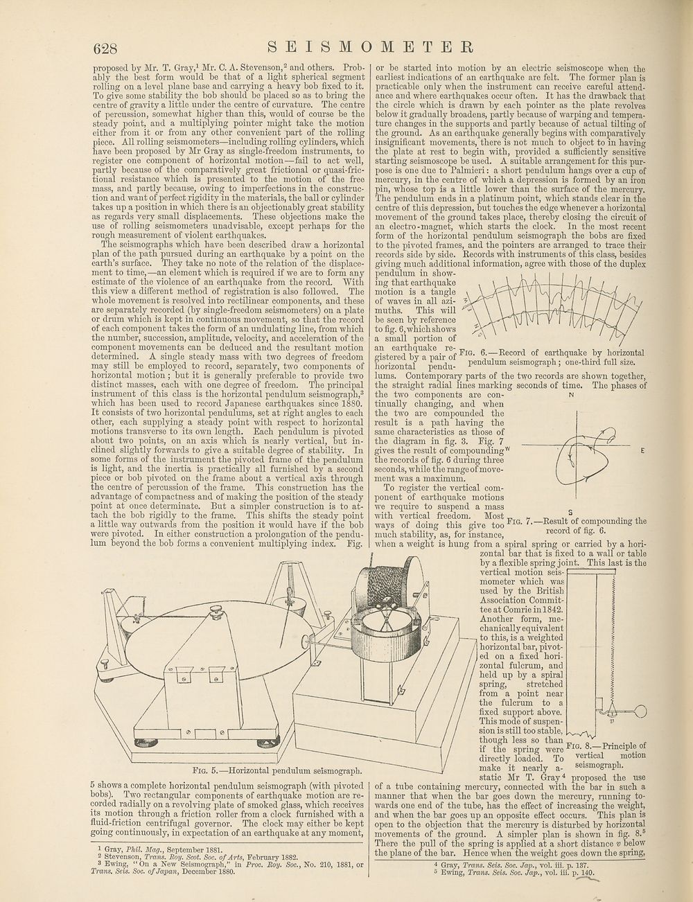
g?steeraedthbyUapeairrofFlG- 6j7Rec0rd of earthquake by horizontal
horizontal pendu- Pendulum seismograph; one-third full size.
lums. Contemporary parts of the two records are shown together,
the straight radial lines marking seconds of time. The phases of
the two components are con- n
tinually changing, and when
the two are compounded the
result is a path having the
same characteristics as those of
the diagram in fig. 3. Fig. 7
gives the result of compoundingw
the records of fig. 6 during three
seconds, while the range of move¬
ment was a maximum.
To register the vertical com¬
ponent of earthquake motions
we require to suspend a mass
with vertical freedom. Most ^
ways of doing this give too Fig./.-Result of compounding the
much stability, as, for instance, recor o g. 6.
when a weight is hung from a spiral spring or carried by a hori¬
zontal bar that is fixed to a wall or table
by a flexible spring joint. This last is the
vertical motion seis¬
mometer which was
used by the British
Association Commit¬
tee at Comrie inl842.
Another form, me¬
chanically equivalent
to this, is a weighted
horizontal bar, pivot¬
ed on a fixed hori¬
zontal fulcrum, and
held up by a spiral
spring, stretched
from a point near
the fulcrum to a
fixed support above.
This mode of suspen¬
sion is still too stable,
though less so than
I'wAv
3
Fig. 5.—Horizontal pendulum seismograph.
5 shows a complete horizontal pendulum seismograph (with pivoted
bobs). Two rectangular components of earthquake motion are re¬
corded radially on a revolving plate of smoked glass, which receives
its motion through a friction roller from a clock furnished with a
fluid-friction centrifugal governor. The clock may either be kept
going continuously, in expectation of an earthquake at any moment,
1 Gray, Phil. Mag., September 1881.
2 Stevenson, Trans. Roy. Scot. Soc. of Arts, February 1882.
3 Ewing, “On a New Seismograph,” in Proc. Roy. Soc., No. 210, 1881, or
Trans. Seis. Soc. of Japan, December 1880.
Fig. 8.—Principle of
directly Ibaded. To verticnl ,motion
make it nearly a- seismograph,
static Mr T. Gray4 proposed the use
of a tube containing mercury, connected with the bar in such a
manner that when the bar goes down the mercury, running to¬
wards one end of the tube, has the effect of increasing the weight,
and when the bar goes up an opposite effect occurs. This plan is
open to the objection that the mercury is disturbed by horizontal
movements of the ground. A simpler plan is shown in fig. 8.5
There the pull of the spring is applied at a short distance v below
the plane of the bar. Hence when the weight goes down the spring,
4 Gray, Trans. Seis. Soc. Jap., vol. iii. p. 137.
5 Ewing, Trans. Seis. Soc. Jap., vol. iii. p. 140.
SEISMOMETER
proposed by Mr. T. Gray,1 Mr. C. A. Stevenson,2 and others. Prob¬
ably the best form would be that of a light spherical segment
rolling on a level plane base and carrying a heavy bob fixed to it.
To give some stability the bob should be placed so as to bring the
centre of gravity a little under the centre of curvature. The centre
of percussion, somewhat higher than this, would of course be the
steady point, and a multiplying pointer might take the motion
either from it or from any other convenient part of the rolling
piece. All rolling seismometers—including rolling cylinders, which
have been proposed by Mr Gray as single-freedom instruments, to
register one component of horizontal motion—fail to act well,
partly because of the comparatively great frictional or quasi-fric-
tional resistance which is presented to the motion of the free
mass, and partly because, owing to imperfections in the construc¬
tion and want of perfect rigidity in the materials, the ball or cylinder
takes up a position in which there is an objectionably great stability
as regards very small displacements. These objections make the
use of rolling seismometers unadvisable, except perhaps for the
rough measurement of violent earthquakes.
The seismographs which have been described draw a horizontal
plan of the path pursued during an earthquake by a point on the
earth’s surface. They take no note of the relation of the displace¬
ment to time,—an element which is required if we are to form any
estimate of the violence of an earthquake from the record. With
this view a different method of registration is also followed. The
whole movement is resolved into rectilinear components, and these
are separately recorded (by single-freedom seismometers) on a plate
or drum which is kept in continuous movement, so that the record
of each component takes the form of an undulating line, from which
the number, succession, amplitude, velocity, and acceleration of the
component movements can be deduced and the resultant motion
determined. A single steady mass with two degrees of freedom
may still be employed to record, separately, two components of
horizontal motion; but it is generally preferable to provide two
distinct masses, each with one degree of freedom. The principal
instrument of this class is the horizontal pendulum seismograph,3
which has been used to record Japanese earthquakes since 1880.
It consists of two horizontal pendulums, set at right angles to each
other, each supplying a steady point with respect to horizontal
motions transverse to its own length. Each pendulum is pivoted
about two points, on an axis which is nearly vertical, but in¬
clined slightly forwards to give a suitable degree of stability. In
some forms of the instrument the pivoted frame of the pendulum
is light, and the inertia is practically all furnished by a second
piece or bob pivoted on the frame about a vertical axis through
the centre of percussion of the frame. This construction has the
advantage of compactness and of making the position of the steady
point at once determinate. But a simpler construction is to at¬
tach the bob rigidly to the frame. This shifts the steady point
a little way outwards from the position it would have if the bob
were pivoted. In either construction a prolongation of the pendu¬
lum beyond the bob forms a convenient multiplying index. Fig.
or be started into motion by an electric seismoscope when the
earliest indications of an earthquake are felt. The former plan is
practicable only when the instrument can receive careful attend¬
ance and where earthquakes occur often. It has the drawback that
the circle which is drawn by each pointer as the plate revolves
below it gradually broadens, partly because of warping and tempera¬
ture changes in the supports and partly because of actual tilting of
the ground. As an earthquake generally begins with comparatively
insignificant movements, there is not much to object to in having
the plate at rest to begin with, provided a sufficiently sensitive
starting seismoscope be used. A suitable arrangement for this pur¬
pose is one due to Palmieri: a short pendulum hangs over a cup of
mercury, in the centre of which a depression is formed by an iron
pin, whose top is a little lower than the surface of the mercury.
The pendulum ends in a platinum point, which stands clear in the
centre of this depression, but touches the edge whenever a horizontal
movement of the ground takes place, thereby closing the circuit of
an electro-magnet, which starts the clock. In the most recent
form of the horizontal pendulum seismograph the bobs are fixed
to the pivoted frames, and the pointers are arranged to trace their
records side by side. Records with instruments of this class, besides
giving much additional information, agree with those of the duplex
pendulum in show¬
ing that earthquake
motion is a tangle
of waves in all azi¬
muths. This will
be seen by reference
to fig. 6, which shows
a small portion of
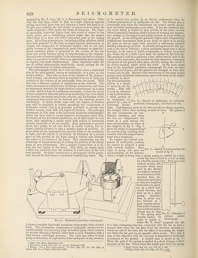
g?steeraedthbyUapeairrofFlG- 6j7Rec0rd of earthquake by horizontal
horizontal pendu- Pendulum seismograph; one-third full size.
lums. Contemporary parts of the two records are shown together,
the straight radial lines marking seconds of time. The phases of
the two components are con- n
tinually changing, and when
the two are compounded the
result is a path having the
same characteristics as those of
the diagram in fig. 3. Fig. 7
gives the result of compoundingw
the records of fig. 6 during three
seconds, while the range of move¬
ment was a maximum.
To register the vertical com¬
ponent of earthquake motions
we require to suspend a mass
with vertical freedom. Most ^
ways of doing this give too Fig./.-Result of compounding the
much stability, as, for instance, recor o g. 6.
when a weight is hung from a spiral spring or carried by a hori¬
zontal bar that is fixed to a wall or table
by a flexible spring joint. This last is the
vertical motion seis¬
mometer which was
used by the British
Association Commit¬
tee at Comrie inl842.
Another form, me¬
chanically equivalent
to this, is a weighted
horizontal bar, pivot¬
ed on a fixed hori¬
zontal fulcrum, and
held up by a spiral
spring, stretched
from a point near
the fulcrum to a
fixed support above.
This mode of suspen¬
sion is still too stable,
though less so than
I'wAv
3
Fig. 5.—Horizontal pendulum seismograph.
5 shows a complete horizontal pendulum seismograph (with pivoted
bobs). Two rectangular components of earthquake motion are re¬
corded radially on a revolving plate of smoked glass, which receives
its motion through a friction roller from a clock furnished with a
fluid-friction centrifugal governor. The clock may either be kept
going continuously, in expectation of an earthquake at any moment,
1 Gray, Phil. Mag., September 1881.
2 Stevenson, Trans. Roy. Scot. Soc. of Arts, February 1882.
3 Ewing, “On a New Seismograph,” in Proc. Roy. Soc., No. 210, 1881, or
Trans. Seis. Soc. of Japan, December 1880.
Fig. 8.—Principle of
directly Ibaded. To verticnl ,motion
make it nearly a- seismograph,
static Mr T. Gray4 proposed the use
of a tube containing mercury, connected with the bar in such a
manner that when the bar goes down the mercury, running to¬
wards one end of the tube, has the effect of increasing the weight,
and when the bar goes up an opposite effect occurs. This plan is
open to the objection that the mercury is disturbed by horizontal
movements of the ground. A simpler plan is shown in fig. 8.5
There the pull of the spring is applied at a short distance v below
the plane of the bar. Hence when the weight goes down the spring,
4 Gray, Trans. Seis. Soc. Jap., vol. iii. p. 137.
5 Ewing, Trans. Seis. Soc. Jap., vol. iii. p. 140.
Set display mode to:
![]() Universal Viewer |
Universal Viewer | ![]() Mirador |
Large image | Transcription
Mirador |
Large image | Transcription
Images and transcriptions on this page, including medium image downloads, may be used under the Creative Commons Attribution 4.0 International Licence unless otherwise stated. ![]()
| Encyclopaedia Britannica > Encyclopaedia Britannica > Volume 21, ROT-Siam > (638) Page 628 |
|---|
| Permanent URL | https://digital.nls.uk/193635573 |
|---|
| Attribution and copyright: |
|
|---|---|
| Shelfmark | EB.17 |
|---|---|
| Description | Ten editions of 'Encyclopaedia Britannica', issued from 1768-1903, in 231 volumes. Originally issued in 100 weekly parts (3 volumes) between 1768 and 1771 by publishers: Colin Macfarquhar and Andrew Bell (Edinburgh); editor: William Smellie: engraver: Andrew Bell. Expanded editions in the 19th century featured more volumes and contributions from leading experts in their fields. Managed and published in Edinburgh up to the 9th edition (25 volumes, from 1875-1889); the 10th edition (1902-1903) re-issued the 9th edition, with 11 supplementary volumes. |
|---|---|
| Additional NLS resources: |
|