New volumes of the Encyclopædia Britannica > Volume 30, K-MOR
(631) Page 597
Download files
Complete book:
Individual page:
Thumbnail gallery: Grid view | List view
MEASURING INSTRUMENTS, ELECTRIC 597
disc is immersed in a chamber filled with mercury, and the current
to be measured passes radially through it from the circumference
to the centre. Under the influence of the magnetic field which is
created in a direction perpendicular to the plane of the disc, this
disc is set in rotation ; the associated disc is also rotating in the
magnetic field, and is retarded by the so-called magnetic friction
due* to eddy currents set up in its mass. In these circumstances
the speed of rotation of the two discs can be adjusted to be propor¬
tional to the current passing through the instrument, and hence
the number of rotations in a given time is a measure of the electric
quantity passed through the meter. Mordey and Flicker have
designed an ingenious meter of a very simple character. A slate
disc°has a number of soft iron wires inserted in it. This is attached
to the escapement wheel of a clock which has no pendulum or hair¬
spring. The disc is included within a coil through which the
current to be measured passes. When the current flows, it creates
a magnetic field which pulls the iron wires into line with it, and
owing to the inertia of the disc an oscillating motion is produced.
The rate of going of the clock is therefore proportional to the
current, and its registration to the electric quantity which has
passed.
Intermittent Integrating Meters.—All the above forms of house
meters are called continuously integrating meters, in that the
operation of recording or obtaining the time-integral of the current
or the power is continuous. There is, however, a large class of
meters known as intermittent integrating meters, which consist of
two parts. The first is simply an ammeter or a wattmeter, while
the second is simply a clock, provided with a mechanism by which
the deflection of the ammeter or wattmeter is recorded at regular
time-intervals, and the records added up. A good example of such
an instrument is that of Johnson and Phillips. This instrument
comprises an electrically-driven clock, which operates a counting
mechanism through a gearing whose ratio is controlled by the
current passing into the circuit. The ammeter part of the instru¬
ment is a coil of wire, through which the current to be integrated
passes, and into which a soft iron plunger is drawn down by the
magnetic force. The degree to which this plunger is sucked in
regulates the amount by which the clock mechanism advances the
recording mechanism at each revolution ; hence the number of
revolutions of the counting dials in any time is proportional to the
time and to the deflection of the ammeter needle—that is, to the
total quantity of electricity which has passed through the meter.
Different opinions are held by electricians as to the relative
advantages of quantity and energy meters. Generally speak¬
ing, quantity meters have the advantage of simplicity of con¬
struction ; but energy meters must be employed if true electric
power is to be measured on a circuit where the voltage is constantly
fluctuating. Intermittent integrating meters are not suitable for
use in cases in which the current is liable to suffer very large varia¬
tions in strength enduring but a short time, as in the case of the
electric supply to a theatre. The ampere-hour meters as a rule
absorb less energy internally than the watt-hour meters. Watt-
hour meters must, however, be employed if the supply is by alter¬
nating currents and the power-absorbing devices are inductive,
such as electric motors.
Instruments for the measurement of electric resistance
are called either Bridges or Ohmmeters. The simplest
and most common form of resistance balance
mmeters. .g ^jiaq ]inown as Wheatstone’s bridge. As
generally used in the laboratory, it consists of a box
containing three sets of resistance coils; two of these
sets are called the two ratio arms, while the third is the
measuring arm. These coils are all joined up in series.
In one ordinary form of Wheatstone’s bridge, known as
the series pattern plug-resistance bridge, there are a series
of coils, two 1-ohm coils, two 10-ohm coils, two 100-ohm
coils, and two 1000-ohm coils. These are joined up in
series in the order 1000, 100, 10, 1; 1, 10, 100, 1000,
and the junctions between each pair are connected to
brass blocks, a series of which are mounted upon an
ebonite slab that forms the top of the box. The blocks
are bored out with a hole partly in one block and partly
in the other, so that they can be connected by accurately-
fitting conical plugs. When the blocks are interconnected
by the plugs, all the coils are short-circuited; but if the
plug or plugs are taken out, then a current flowing from
one end of the series to the other is compelled to pass
through the corresponding coils. In series with this set of
coils is another set, the resistances of which are generally
1, 2, 3, 4, 10, 20, 30, 40, 100, 200, 300, 400, 1000, 2000,
3000, 4000 ohms. These form the measuring arm, and
the junction between each pair of coils is connected as
above described to a block, the blocks being interconnected
by plugs. This series of coils is joined up with the re¬
sistance to be measured, and a galvanometer and a battery
are added, as shown in Fig. 5.
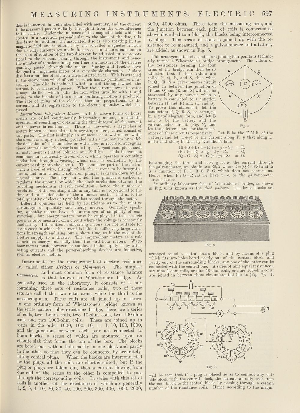
This arrangement of six conductors joining four points is technic¬
ally termed a Wheatstone’s bridge arrangement. The values of
the resistances forming the four
arms of the bridge can then be so
adjusted that if their values are
called P, Q, R, and S, then when
P : Q : ; R : S a galvanometer circuit
joined in between the junction of
(P and Q) and (R and S) will not be
traversed by any current when a
battery is connected to a junction
between (P and R) and (Q and S).
To prove this statement, let the
conductors P, Q, R, S, be arranged
in a parallelogram form, and let B
and G be the battery and the
galvanometer circuit (Fig. 5), and
let these letters stand for the resist¬
ances of these circuits respectively. Let E be the E.M.F. of the
battery, and let (x + y) be the current along P, y that along Q,
and z that along B, then by Kirchhoff’s laws
(R + S + B) z-R {x + y)- Sy = E,
(P + G + R) x + y- Gy - Rz = O,
(Q + G + S) ?/-G (a: + 2/)-Sz = O.
Rearranging the terms and solving for x, the current through
the galvanometer, we obtain ai = Eo/A where 5 = (QR - PS) and A
is a function of P, Q, R, S, B, G, which does not concern us.
Hence when P : Q = R : S we have x = o, or the galvanometer
current is zero.
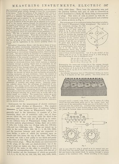
An ordinary laboratory form of Wheatstone’s bridge, as shown
in Fig. 6, is known as the dial pattern. Ten brass blocks are
Fig. 6
arranged round a central brass block, and by means of a plug
which fits into holes bored partly out of the central block and
partly out of the surrounding blocks, any one of the latter can be
connected with the central one. A series of nine equal resistances,
say nine 1-ohm coils, or nine 10-ohm coils, or nine 100-ohm coils,
are joined in between these circumferential blocks (Fig. 7). It
will be seen that if a plug is placed so as to connect any out¬
side block with the central block, the current can only pass from
the zero block to the central block by passing through a certain
number of the resistance coils. Hence according to the magni-
disc is immersed in a chamber filled with mercury, and the current
to be measured passes radially through it from the circumference
to the centre. Under the influence of the magnetic field which is
created in a direction perpendicular to the plane of the disc, this
disc is set in rotation ; the associated disc is also rotating in the
magnetic field, and is retarded by the so-called magnetic friction
due* to eddy currents set up in its mass. In these circumstances
the speed of rotation of the two discs can be adjusted to be propor¬
tional to the current passing through the instrument, and hence
the number of rotations in a given time is a measure of the electric
quantity passed through the meter. Mordey and Flicker have
designed an ingenious meter of a very simple character. A slate
disc°has a number of soft iron wires inserted in it. This is attached
to the escapement wheel of a clock which has no pendulum or hair¬
spring. The disc is included within a coil through which the
current to be measured passes. When the current flows, it creates
a magnetic field which pulls the iron wires into line with it, and
owing to the inertia of the disc an oscillating motion is produced.
The rate of going of the clock is therefore proportional to the
current, and its registration to the electric quantity which has
passed.
Intermittent Integrating Meters.—All the above forms of house
meters are called continuously integrating meters, in that the
operation of recording or obtaining the time-integral of the current
or the power is continuous. There is, however, a large class of
meters known as intermittent integrating meters, which consist of
two parts. The first is simply an ammeter or a wattmeter, while
the second is simply a clock, provided with a mechanism by which
the deflection of the ammeter or wattmeter is recorded at regular
time-intervals, and the records added up. A good example of such
an instrument is that of Johnson and Phillips. This instrument
comprises an electrically-driven clock, which operates a counting
mechanism through a gearing whose ratio is controlled by the
current passing into the circuit. The ammeter part of the instru¬
ment is a coil of wire, through which the current to be integrated
passes, and into which a soft iron plunger is drawn down by the
magnetic force. The degree to which this plunger is sucked in
regulates the amount by which the clock mechanism advances the
recording mechanism at each revolution ; hence the number of
revolutions of the counting dials in any time is proportional to the
time and to the deflection of the ammeter needle—that is, to the
total quantity of electricity which has passed through the meter.
Different opinions are held by electricians as to the relative
advantages of quantity and energy meters. Generally speak¬
ing, quantity meters have the advantage of simplicity of con¬
struction ; but energy meters must be employed if true electric
power is to be measured on a circuit where the voltage is constantly
fluctuating. Intermittent integrating meters are not suitable for
use in cases in which the current is liable to suffer very large varia¬
tions in strength enduring but a short time, as in the case of the
electric supply to a theatre. The ampere-hour meters as a rule
absorb less energy internally than the watt-hour meters. Watt-
hour meters must, however, be employed if the supply is by alter¬
nating currents and the power-absorbing devices are inductive,
such as electric motors.
Instruments for the measurement of electric resistance
are called either Bridges or Ohmmeters. The simplest
and most common form of resistance balance
mmeters. .g ^jiaq ]inown as Wheatstone’s bridge. As
generally used in the laboratory, it consists of a box
containing three sets of resistance coils; two of these
sets are called the two ratio arms, while the third is the
measuring arm. These coils are all joined up in series.
In one ordinary form of Wheatstone’s bridge, known as
the series pattern plug-resistance bridge, there are a series
of coils, two 1-ohm coils, two 10-ohm coils, two 100-ohm
coils, and two 1000-ohm coils. These are joined up in
series in the order 1000, 100, 10, 1; 1, 10, 100, 1000,
and the junctions between each pair are connected to
brass blocks, a series of which are mounted upon an
ebonite slab that forms the top of the box. The blocks
are bored out with a hole partly in one block and partly
in the other, so that they can be connected by accurately-
fitting conical plugs. When the blocks are interconnected
by the plugs, all the coils are short-circuited; but if the
plug or plugs are taken out, then a current flowing from
one end of the series to the other is compelled to pass
through the corresponding coils. In series with this set of
coils is another set, the resistances of which are generally
1, 2, 3, 4, 10, 20, 30, 40, 100, 200, 300, 400, 1000, 2000,
3000, 4000 ohms. These form the measuring arm, and
the junction between each pair of coils is connected as
above described to a block, the blocks being interconnected
by plugs. This series of coils is joined up with the re¬
sistance to be measured, and a galvanometer and a battery
are added, as shown in Fig. 5.
This arrangement of six conductors joining four points is technic¬
ally termed a Wheatstone’s bridge arrangement. The values of
the resistances forming the four
arms of the bridge can then be so
adjusted that if their values are
called P, Q, R, and S, then when
P : Q : ; R : S a galvanometer circuit
joined in between the junction of
(P and Q) and (R and S) will not be
traversed by any current when a
battery is connected to a junction
between (P and R) and (Q and S).
To prove this statement, let the
conductors P, Q, R, S, be arranged
in a parallelogram form, and let B
and G be the battery and the
galvanometer circuit (Fig. 5), and
let these letters stand for the resist¬
ances of these circuits respectively. Let E be the E.M.F. of the
battery, and let (x + y) be the current along P, y that along Q,
and z that along B, then by Kirchhoff’s laws
(R + S + B) z-R {x + y)- Sy = E,
(P + G + R) x + y- Gy - Rz = O,
(Q + G + S) ?/-G (a: + 2/)-Sz = O.
Rearranging the terms and solving for x, the current through
the galvanometer, we obtain ai = Eo/A where 5 = (QR - PS) and A
is a function of P, Q, R, S, B, G, which does not concern us.
Hence when P : Q = R : S we have x = o, or the galvanometer
current is zero.
An ordinary laboratory form of Wheatstone’s bridge, as shown
in Fig. 6, is known as the dial pattern. Ten brass blocks are
Fig. 6
arranged round a central brass block, and by means of a plug
which fits into holes bored partly out of the central block and
partly out of the surrounding blocks, any one of the latter can be
connected with the central one. A series of nine equal resistances,
say nine 1-ohm coils, or nine 10-ohm coils, or nine 100-ohm coils,
are joined in between these circumferential blocks (Fig. 7). It
will be seen that if a plug is placed so as to connect any out¬
side block with the central block, the current can only pass from
the zero block to the central block by passing through a certain
number of the resistance coils. Hence according to the magni-
Set display mode to:
![]() Universal Viewer |
Universal Viewer | ![]() Mirador |
Large image | Transcription
Mirador |
Large image | Transcription
Images and transcriptions on this page, including medium image downloads, may be used under the Creative Commons Attribution 4.0 International Licence unless otherwise stated. ![]()
| Encyclopaedia Britannica > New volumes of the Encyclopædia Britannica > Volume 30, K-MOR > (631) Page 597 |
|---|
| Permanent URL | https://digital.nls.uk/193575704 |
|---|
| Attribution and copyright: |
|
|---|---|
| Shelfmark | EB.18 |
|---|---|
| Description | Ten editions of 'Encyclopaedia Britannica', issued from 1768-1903, in 231 volumes. Originally issued in 100 weekly parts (3 volumes) between 1768 and 1771 by publishers: Colin Macfarquhar and Andrew Bell (Edinburgh); editor: William Smellie: engraver: Andrew Bell. Expanded editions in the 19th century featured more volumes and contributions from leading experts in their fields. Managed and published in Edinburgh up to the 9th edition (25 volumes, from 1875-1889); the 10th edition (1902-1903) re-issued the 9th edition, with 11 supplementary volumes. |
|---|---|
| Additional NLS resources: |
|