New volumes of the Encyclopædia Britannica > Volume 30, K-MOR
(628) Page 594
Download files
Complete book:
Individual page:
Thumbnail gallery: Grid view | List view
594 MEASURING INSTRUMENTS, ELECTRIC
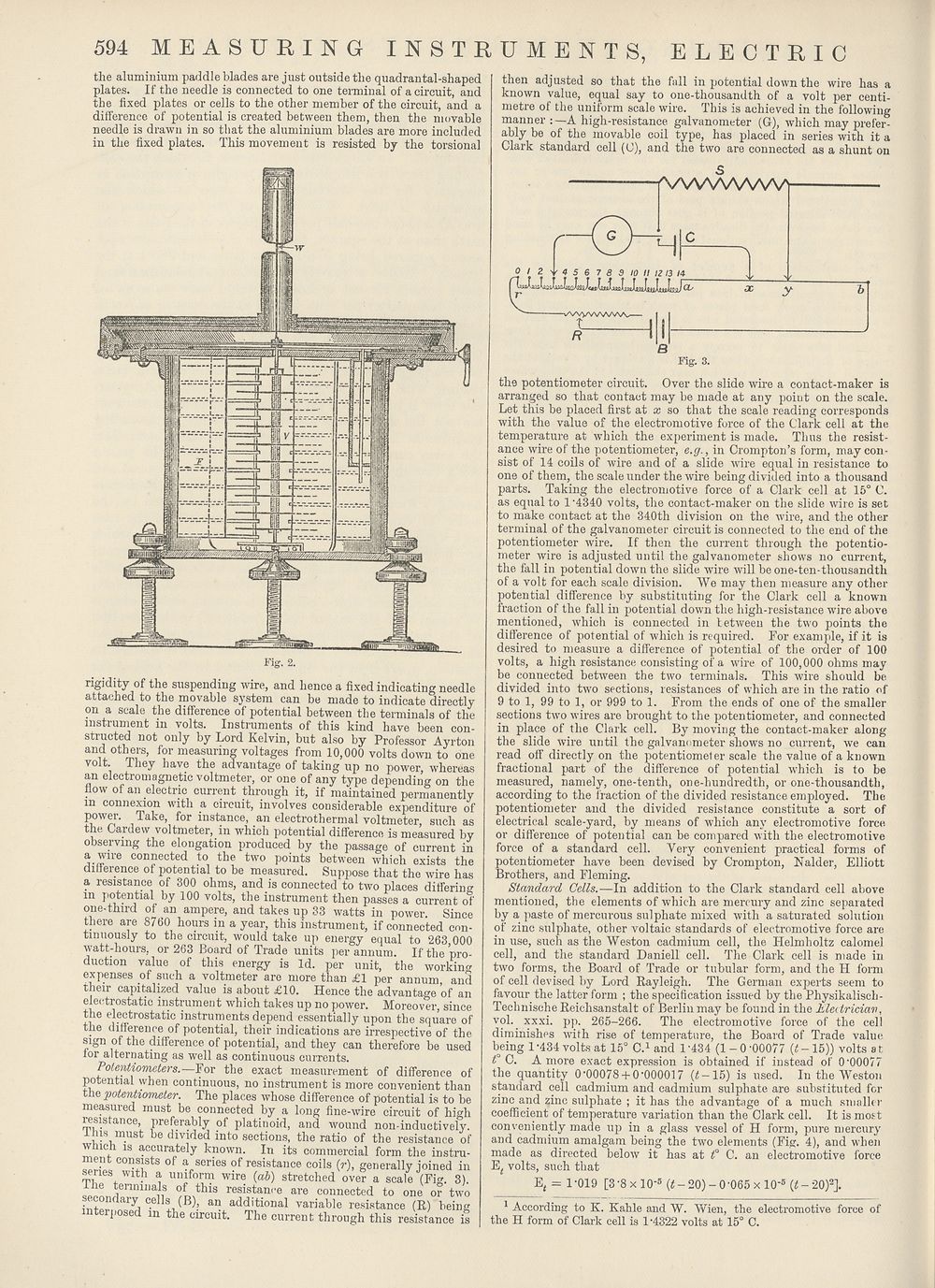
the aluminium paddle blades are just outside the quadrantal-shaped
plates. If the needle is connected to one terminal of a circuit, and
the fixed plates or cells to the other member of the circuit, and a
difference of potential is created between them, then the movable
needle is drawn in so that the aluminium blades are more included
in the fixed plates. This movement is resisted by the torsional
Fig. 2.
rigidity of the suspending wire, and hence a fixed indicating needle
attached to the movable system can be made to indicate directly
on a scale the difference of potential between the terminals of the
instrument in volts. Instruments of this kind have been con¬
structed not only by Lord Kelvin, but also by Professor Ayrton
and others, for measuring voltages from 10,000 volts down to one
volt. They have the advantage of taking up no power, whereas
an electromagnetic voltmeter, or one of any type depending on the
flow of an electric current through it, if maintained permanently
m connexion with a circuit, involves considerable expenditure of
power. Take, for instance, an electrothermal voltmeter, such as
the Gaitlew voltmeter, in which potential difference is measured by
observing the elongation produced by the passage of current in
a wire connected to the two points between which exists the
difference of iiotential to be measured. Suppose that the wire has
a resistance of 300 ohms, and is connected to two places differing
in potential by 100 volts, the instrument then passes a current of
one-third of an ampere, and takes up 33 watts in power Since
there are 8760 hours in a year, this instrument, if connected con-
timiously to the circuit, would take up energy equal to 263 000
watt-hours, or 263 Board of Trade units per annum. If the pro¬
duction value of this energy is Id. per unit, the working
expenses of such a voltmeter are more than £1 per annum, and
their capitalized value is about £10. Hence the advantage of an
electrostatic instrument which takes up no power. Moreover, since
the electrostatic instruments depend essentially upon the square of
the difference of potential, their indications are irrespective of the
sign of the difference of potential, and they can therefore be used
for alternating as well as continuous currents.
Potentiometers.—For the exact measurement of difference of
potential when continuous, no instrument is more convenient than
the jMtentiometer. The places whose difference of potential is to be
measured must be connected by a long fine-wire circuit of high
resistance, preferably of platinoid, and wound non-inductively.
lins must be divided into sections, the ratio of the resistance of
which is accurately known. In its commercial form the instru¬
ment consists of a series of resistance coils (r), generally joined in
senes with a uniform wire (ab) stretched over a scale (Fig. 3).
sennnienniliaiiS °,LtluS resistan,'e a™ connected to one or two
secondary cells (B), an additional variable resistance (R) being
interposed m the circuit. The current through this resistance is
then adjusted so that the fall in potential down the wire has a
known value, equal say to one-thousandth of a volt per centi¬
metre of the uniform scale wire. This is achieved in the following
manner : —A high-resistance galvanometer (G), which may prefer¬
ably be of the movable coil type, has placed in series with it a
Clark standard cell (O), and the two are connected as a shunt on
6
Fig. 3.
the potentiometer circuit. Over the slide wire a contact-maker is
arranged so that contact may be made at any point on the scale.
Let this be placed first at x so that the scale reading corresponds
with the value of the electromotive force of the Clark cell at the
temperature at which the experiment is made. Thus the resist¬
ance wire of the potentiometer, e.g., in Crompton’s form, may con¬
sist of 14 coils of wire and of a slide wire equal in resistance to
one of them, the scale under the wire being divided into a thousand
parts. Taking the electromotive force of a Clark cell at 15° C.
as equal to 1 ’4340 volts, the contact-maker on the slide wire is set
to make contact at the 340th division on the wire, and the other
terminal of the galvanometer circuit is connected to the end of the
potentiometer wire. If then the current through the potentio¬
meter wire is adjusted until the galvanometer shows no current,
the fall in potential down the slide wire will be one-ten-thousandth
of a volt for each scale division. We may then measure any other
potential difference by substituting for the Clark cell a known
fraction of the fall in potential down the high-resistance wire above
mentioned, which is connected in between the two points the
difference of potential of which is required. For example, if it is
desired to measure a difference of potential of the order of 100
volts, a high resistance consisting of a wire of 100,000 ohms may
be connected between the two terminals. This wire should be
divided into two sections, resistances of which are in the ratio of
9 to 1, 99 to 1, or 999 to 1. From the ends of one of the smaller
sections two wires are brought to the potentiometer, and connected
in place of the Clark cell. By moving the contact-maker along
the slide wire until the galvanometer shows no current, we can
read off directly on the potentiometer scale the value of a known
fractional part of the difference of potential which is to be
measured, namely, one-tenth, one-hundredth, or one-thousandth,
according to the fraction of the divided resistance employed. The
potentiometer and the divided resistance constitute a sort of
electrical scale-yard, by means of which any electromotive force
or difference of potential can be compared with the electromotive
force of a standard cell. Very convenient practical forms of
potentiometer have been devised by Crompton, Nalder, Elliott
Brothers, and Fleming.
Standard Cells.—In addition to the Clark standard cell above
mentioned, the elements of which are mercury and zinc separated
by a paste of mercurous sulphate mixed with a saturated solution
of zinc sulphate, other voltaic standards of electromotive force are
in use, such as the Weston cadmium cell, the Helmholtz calomel
cell, and the standard Daniell cell. The Clark cell is made in
two forms, the Board of Trade or tubular form, and the H form
of cell devised by Lord Rayleigh. The German experts seem to
favour the latter form ; the specification issued by the Physikalisch-
Technische Reichsanstalt of Berlin may be found in the Electrician,
vql. xxxi. pp. 265-266. The electromotive force of the cell
diminishes with rise of temperature, the Board of Trade value
being 1 -434 volts at 15° C.1 and 1 ’434 (1-0 '00077 {t - 15)) volts a t
1° C. A more exact expression is obtained if instead of 0'00077
the quantity 0'00078 + 0'000017 (£-15) is used. In the Weston
standard cell cadmium and cadmium sulphate are substituted for
zinc and zinc sulphate ; it has the advantage of a much smaller
coefficient of temperature variation than the Clark cell. It is most
conveniently made up in a glass vessel of H form, pure mercury
and cadmium amalgam being the two elements (Fig. 4), and when
made as directed below it has at £° C. an electromotive force
E/ volts, such that
Ef = 1-019 [3'8 xlO-5 (£ - 20) - 0 '065 x 10’5 {t - 20)2].
1 According to K. Kahle and W. Wien, the electromotive force of
the H form of Clark cell is 1'4322 volts at 15° C.
J2 L z. Y 4 5 6. 7 8 9 10 II 12 13 14
y
WVVWWWV
t
Set display mode to:
![]() Universal Viewer |
Universal Viewer | ![]() Mirador |
Large image | Transcription
Mirador |
Large image | Transcription
Images and transcriptions on this page, including medium image downloads, may be used under the Creative Commons Attribution 4.0 International Licence unless otherwise stated. ![]()
| Encyclopaedia Britannica > New volumes of the Encyclopædia Britannica > Volume 30, K-MOR > (628) Page 594 |
|---|
| Permanent URL | https://digital.nls.uk/193575665 |
|---|
| Attribution and copyright: |
|
|---|---|
| Shelfmark | EB.18 |
|---|---|
| Description | Ten editions of 'Encyclopaedia Britannica', issued from 1768-1903, in 231 volumes. Originally issued in 100 weekly parts (3 volumes) between 1768 and 1771 by publishers: Colin Macfarquhar and Andrew Bell (Edinburgh); editor: William Smellie: engraver: Andrew Bell. Expanded editions in the 19th century featured more volumes and contributions from leading experts in their fields. Managed and published in Edinburgh up to the 9th edition (25 volumes, from 1875-1889); the 10th edition (1902-1903) re-issued the 9th edition, with 11 supplementary volumes. |
|---|---|
| Additional NLS resources: |
|