New volumes of the Encyclopædia Britannica > Volume 30, K-MOR
(617) Page 583
Download files
Complete book:
Individual page:
Thumbnail gallery: Grid view | List view
MATHEMATICAL INSTRUMENTS 583
the wheel, the spindle has an arm GH, which is kept parallel to a
similar arm attached to K perpendicular to DB. The plane of the
knife-edge wheel r is therefore always parallel to DB. If now the
point B is made to follow a curve whose y is measured from OX,
we have in the triangle BDB', with the angle </> at D,
tan <t> — yla,
where « = DB' is the constant base to which the instrument works.
The point of contact of the wheel r or any point of the carriage 0
will therefore always move in a direction making an angle <p with
the axis of x, whilst it moves in the cc-direction through the same
distance as the point B on the y-curve—that is to say, it will trace
out the integral curve required, and so will any point rigidly
connected with the carriage C. A pen P attached to this carriage
will therefore draw the integral curve. Instead of moving B
along the y-curve, a tracer T fixed to the carriage A is guided
along it. For using the instrument the carriage is placed on
the drawing-board with the front edge parallel to the axis of y,
the carriage A being clamped in the central position with B on
the axis AE. The tracer is then placed on the a:-axis of the
?/-curve and clamped to the carriage, and the instrument is ready
for use. As it is convenient to have the integral curve placed directly
opposite to the y-curve so that corresponding values of y or Y
are drawn on the same line, a pen P' is fixed to C in a line with
the tracer.
Boys’ integraph was invented during a sleepless night, and
during the following days carried out as a working model,
which gives highly satisfactory results. It is ingenious in its
simplicity, and a direct realization as a mechanism of the principles
explained in connexion with Fig. 21. The line B'B is repre¬
sented by the edge of an ordinary T-square sliding against the
edge of a drawing-board. The points B and P are connected by
two rods BE and EP, jointed at E. At B, E, and P are small
pulleys of equal diameters. Over these an endless string runs,
ensuring that the pulleys at B and P always turn through equal
! angles. The pulley at B is fixed to a rod which passes through
the point D, which itself is fixed in the T-square. The pulley at
P carries the knife-edge wheel. If then B and P are kept on the
edge of the T-square, and B is guided along the curve, the wheel at
Pwill roll along the Y-curve, it having been originally set parallel
to BD. To give the wheel at P sufficient grip on the paper, a small
loaded three-wheeled carriage, the knife-edge wheel P being one
of its wheels, is added. If a piece of copying paper is inserted
between the wheel P and the drawing paper the Y-curve is drawn
very sharply.
Integraphs have also been constructed, by aid of which ordinary
differential equations, especially linear ones, can be solved, the solu¬
tion being given as a curve. The first suggestion in this direction
was made by Lord Kelvin. So far no really useful instrument has
been made, although the ideas seem sufficiently developed to enable
a skilful instrument-maker to produce one should there be sufficient
demand for it. Sometimes a combination of graphical work with
an integraph will serve the purpose. This is the case if the vari¬
ables are separated, hence if the equation
'Kdx + Ydy^o
has to be integrated where X=p(a;), Y — (f>(y) are given as curves.
If we write
then u as a function of x, and as a function of y can be graphically
found by the integraph. The general solution is then
u + v=c
with the condition, for the determination for c, that y=y0, for
x — x0. This determines c = M0 + r0, where and v0 are known from
the graphs of u and v. From this the solution as a curve giving y
a function of x can be drawn :—For any x take u from its graph,
and find the y for which v = c-u, plotting these y against their x
gives the curve required.
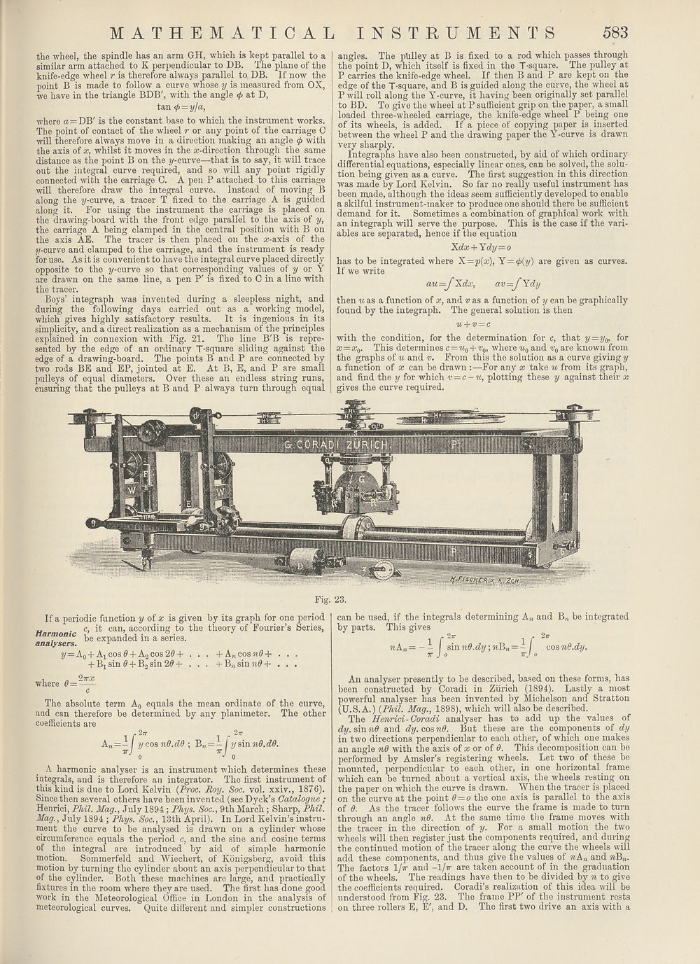
Fig. 23.
If a periodic function y of x is given by its graph for one period
„ . c, it can, according to the theory of Fourier’s Series,
Harmonic be nded in a Series.
analysers. r
2/=Ao + A1cos0 + A2cos20+ . . . +A„cosn0+ . . .
+ Bisin 0 + B2sin 20 + . . . + B,4siun0+ . . .
where 6 =
‘lirx
c
The absolute term A0 equals the mean ordinate of the curve,
and can therefore be determined by any planimeter. The other
coefficients are
2jr ^ ^ 27r
y cos nd.dd ; B„ = - / ?/sin«0.c?0.
A harmonic analyser is an instrument which determines these
integrals, and is therefore an integrator. The first instrument of
this kind, is due to Lord Kelvin (Proc. Roy. Soc. vol. xxiv., 1876).
Since then several others have been invented (see Dyck’s Catalogue ;
Henrici, Phil. Mag., July 1894 ; Phys. Soc., 9th March ; Sharp, Phil.
Mag., July 1894 ; Phys. Soc., 13th April). In Lord Kelvin’s instru¬
ment the curve to be analysed is drawn on a cylinder whose
circumference equals the period c, and the sine and cosine terms
of the integral are introduced by aid of simple harmonic
motion. Sommerfeld and Wiechert, of Konigsberg, avoid this
motion by turning the cylinder about an axis perpendicular to that
of the cylinder. Both these machines are large, and practically
fixtures in the room where they are used. The first has done good
work in the Meteorological Office in London in the analysis of
meteorological curves. Quite different and simpler constructions
can be used, if the integrals determining A„ and B„ be integrated
An analyser presently to be described, based on these forms, has
been constructed by Coradi in Zurich (1894). Lastly a most
powerful analyser has been invented by Michelson and Stratton
(U.S.A.) (Phil. Mag., 1898), which will also be described.
The Henrici- Coradi analyser has to add up the values of
dy. sin n8 and dy. cos nd. But these are the components of dy
in two directions perpendicular to each other, of which one makes
an angle nd with the axis of x or of 0. Tins decomposition can be
performed by Amsler’s registering wheels. Let two of these be
mounted, perpendicular to each other, in one horizontal frame
which can be turned about a vertical axis, the wheels resting on
the paper on which the curve is drawn. When the tracer is placed
on the curve at the point 0 = o the one axis is parallel to the axis
of 0. As the tracer follows the curve the frame is made to turn
through an angle nd. At the same time the frame moves with
the tracer in the direction of y. For a small motion the two
wheels will then register just the components required, and during
the continued motion of the tracer along the curve the wheels will
add these components, and thus give the values of nKn and riP>n.
The factor's 1/tt and -I/tt are taken account of in the graduation
of the wheels. The readings have then to be divided by n to give
the coefficients required. Coradi’s realization of this idea will be
understood from Fig. 23. The frame PP' of the instrument rests
on three rollers E, E', and D. The first two drive an axis with a
the wheel, the spindle has an arm GH, which is kept parallel to a
similar arm attached to K perpendicular to DB. The plane of the
knife-edge wheel r is therefore always parallel to DB. If now the
point B is made to follow a curve whose y is measured from OX,
we have in the triangle BDB', with the angle </> at D,
tan <t> — yla,
where « = DB' is the constant base to which the instrument works.
The point of contact of the wheel r or any point of the carriage 0
will therefore always move in a direction making an angle <p with
the axis of x, whilst it moves in the cc-direction through the same
distance as the point B on the y-curve—that is to say, it will trace
out the integral curve required, and so will any point rigidly
connected with the carriage C. A pen P attached to this carriage
will therefore draw the integral curve. Instead of moving B
along the y-curve, a tracer T fixed to the carriage A is guided
along it. For using the instrument the carriage is placed on
the drawing-board with the front edge parallel to the axis of y,
the carriage A being clamped in the central position with B on
the axis AE. The tracer is then placed on the a:-axis of the
?/-curve and clamped to the carriage, and the instrument is ready
for use. As it is convenient to have the integral curve placed directly
opposite to the y-curve so that corresponding values of y or Y
are drawn on the same line, a pen P' is fixed to C in a line with
the tracer.
Boys’ integraph was invented during a sleepless night, and
during the following days carried out as a working model,
which gives highly satisfactory results. It is ingenious in its
simplicity, and a direct realization as a mechanism of the principles
explained in connexion with Fig. 21. The line B'B is repre¬
sented by the edge of an ordinary T-square sliding against the
edge of a drawing-board. The points B and P are connected by
two rods BE and EP, jointed at E. At B, E, and P are small
pulleys of equal diameters. Over these an endless string runs,
ensuring that the pulleys at B and P always turn through equal
! angles. The pulley at B is fixed to a rod which passes through
the point D, which itself is fixed in the T-square. The pulley at
P carries the knife-edge wheel. If then B and P are kept on the
edge of the T-square, and B is guided along the curve, the wheel at
Pwill roll along the Y-curve, it having been originally set parallel
to BD. To give the wheel at P sufficient grip on the paper, a small
loaded three-wheeled carriage, the knife-edge wheel P being one
of its wheels, is added. If a piece of copying paper is inserted
between the wheel P and the drawing paper the Y-curve is drawn
very sharply.
Integraphs have also been constructed, by aid of which ordinary
differential equations, especially linear ones, can be solved, the solu¬
tion being given as a curve. The first suggestion in this direction
was made by Lord Kelvin. So far no really useful instrument has
been made, although the ideas seem sufficiently developed to enable
a skilful instrument-maker to produce one should there be sufficient
demand for it. Sometimes a combination of graphical work with
an integraph will serve the purpose. This is the case if the vari¬
ables are separated, hence if the equation
'Kdx + Ydy^o
has to be integrated where X=p(a;), Y — (f>(y) are given as curves.
If we write
then u as a function of x, and as a function of y can be graphically
found by the integraph. The general solution is then
u + v=c
with the condition, for the determination for c, that y=y0, for
x — x0. This determines c = M0 + r0, where and v0 are known from
the graphs of u and v. From this the solution as a curve giving y
a function of x can be drawn :—For any x take u from its graph,
and find the y for which v = c-u, plotting these y against their x
gives the curve required.
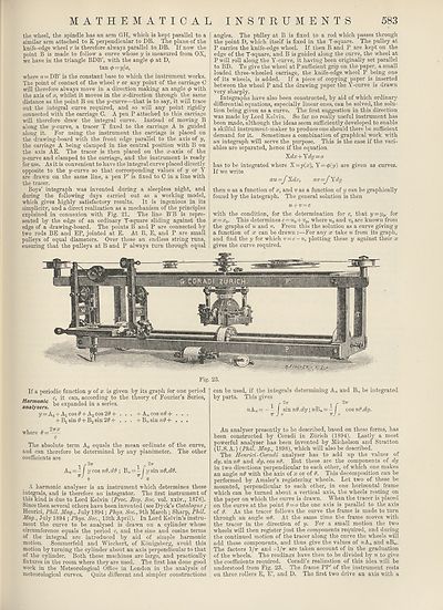
Fig. 23.
If a periodic function y of x is given by its graph for one period
„ . c, it can, according to the theory of Fourier’s Series,
Harmonic be nded in a Series.
analysers. r
2/=Ao + A1cos0 + A2cos20+ . . . +A„cosn0+ . . .
+ Bisin 0 + B2sin 20 + . . . + B,4siun0+ . . .
where 6 =
‘lirx
c
The absolute term A0 equals the mean ordinate of the curve,
and can therefore be determined by any planimeter. The other
coefficients are
2jr ^ ^ 27r
y cos nd.dd ; B„ = - / ?/sin«0.c?0.
A harmonic analyser is an instrument which determines these
integrals, and is therefore an integrator. The first instrument of
this kind, is due to Lord Kelvin (Proc. Roy. Soc. vol. xxiv., 1876).
Since then several others have been invented (see Dyck’s Catalogue ;
Henrici, Phil. Mag., July 1894 ; Phys. Soc., 9th March ; Sharp, Phil.
Mag., July 1894 ; Phys. Soc., 13th April). In Lord Kelvin’s instru¬
ment the curve to be analysed is drawn on a cylinder whose
circumference equals the period c, and the sine and cosine terms
of the integral are introduced by aid of simple harmonic
motion. Sommerfeld and Wiechert, of Konigsberg, avoid this
motion by turning the cylinder about an axis perpendicular to that
of the cylinder. Both these machines are large, and practically
fixtures in the room where they are used. The first has done good
work in the Meteorological Office in London in the analysis of
meteorological curves. Quite different and simpler constructions
can be used, if the integrals determining A„ and B„ be integrated
An analyser presently to be described, based on these forms, has
been constructed by Coradi in Zurich (1894). Lastly a most
powerful analyser has been invented by Michelson and Stratton
(U.S.A.) (Phil. Mag., 1898), which will also be described.
The Henrici- Coradi analyser has to add up the values of
dy. sin n8 and dy. cos nd. But these are the components of dy
in two directions perpendicular to each other, of which one makes
an angle nd with the axis of x or of 0. Tins decomposition can be
performed by Amsler’s registering wheels. Let two of these be
mounted, perpendicular to each other, in one horizontal frame
which can be turned about a vertical axis, the wheels resting on
the paper on which the curve is drawn. When the tracer is placed
on the curve at the point 0 = o the one axis is parallel to the axis
of 0. As the tracer follows the curve the frame is made to turn
through an angle nd. At the same time the frame moves with
the tracer in the direction of y. For a small motion the two
wheels will then register just the components required, and during
the continued motion of the tracer along the curve the wheels will
add these components, and thus give the values of nKn and riP>n.
The factor's 1/tt and -I/tt are taken account of in the graduation
of the wheels. The readings have then to be divided by n to give
the coefficients required. Coradi’s realization of this idea will be
understood from Fig. 23. The frame PP' of the instrument rests
on three rollers E, E', and D. The first two drive an axis with a
Set display mode to:
![]() Universal Viewer |
Universal Viewer | ![]() Mirador |
Large image | Transcription
Mirador |
Large image | Transcription
Images and transcriptions on this page, including medium image downloads, may be used under the Creative Commons Attribution 4.0 International Licence unless otherwise stated. ![]()
| Encyclopaedia Britannica > New volumes of the Encyclopædia Britannica > Volume 30, K-MOR > (617) Page 583 |
|---|
| Permanent URL | https://digital.nls.uk/193575522 |
|---|
| Attribution and copyright: |
|
|---|---|
| Shelfmark | EB.18 |
|---|---|
| Description | Ten editions of 'Encyclopaedia Britannica', issued from 1768-1903, in 231 volumes. Originally issued in 100 weekly parts (3 volumes) between 1768 and 1771 by publishers: Colin Macfarquhar and Andrew Bell (Edinburgh); editor: William Smellie: engraver: Andrew Bell. Expanded editions in the 19th century featured more volumes and contributions from leading experts in their fields. Managed and published in Edinburgh up to the 9th edition (25 volumes, from 1875-1889); the 10th edition (1902-1903) re-issued the 9th edition, with 11 supplementary volumes. |
|---|---|
| Additional NLS resources: |
|