New volumes of the Encyclopædia Britannica > Volume 30, K-MOR
(614) Page 580
Download files
Complete book:
Individual page:
Thumbnail gallery: Grid view | List view
580
MATHEMATICAL INSTRUMENTS
Q'T', and therefore serve to measure the area swept over like the
wheel in the machine already described. The turning of the rod
will also produce slipping of the wheel, but it will be seen without
difficulty that this will cancel during a cyclical motion of the rod,
provided the rod does not perform a whole rotation. _ Messrs Hme
and Robertson, New York, have constructed a planimeter on this
principle, which, however, is only a slight modification of one
described by Amsler in 1856. The end Q of the rod ends in a
button which slides along a Y-groove.
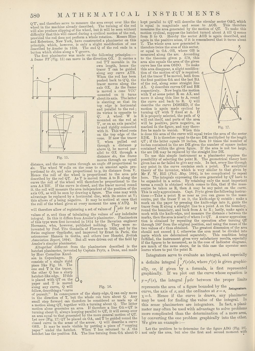
The first planimeter was made on the following principles
A frame FF (Fig. 15) can move in the direction OX. It carries a
rod T'T movable in its
own length, hence the
tracer T can be guided
along any curve ATB.
When the rod has been
pushed back to Q'Q, the
tracer moves along the
axis OX. As the frame
is moved a cone VCC'
mounted on it turns
about its axis. The latter
is slanting so that its
top edge is horizontal
and parallel to the rod ;
its vertex is opposite to
Q\ A wheel W is
mounted on the rod at
T, or on an axis parallel
to and rigidly connected
with it. This wheel rests
on the top edge of the
cone. If now the tracer
T, when pulled out
through a distance y
above Q, be moved par¬
allel to OX through a
distance dx, the frame
moves through an equal
distance, and the cone turns through an angle dO proportional to
dx. The wheel W rolls on the cone to an amount again pro¬
portional to dx, and also proportional to y, its distance from V.
Hence the roll of the wheel is proportional to the area ydx
described by the rod QT. As T is moved from A to B along the
curve the roll of the wheel will therefore be proportional to the
area AA'BB'. If the curve is closed, and the tracer moved round
it, the roll will measure the area independent of the position of the
axis OX, as will be seen by drawing a figure. The. cone may with
advantage be replaced by a horizontal disc, with its centre at A ;
this allows of y being negative. It may be noticed at once that
the roll of the wheel gives at every moment the area A'ATQ. It
will therefore allow of registering a set of values of /: ydx for any
values of x, and thus of tabulating the values of any indefinite
integral. In this it differs from Amsler’s planimeter. .Planiineters
of this type were first invented in 1814 by the Bavarian engineer
Hermann, who, however, published nothing. They were re¬
invented by Prof. Tito Gonnella of Florence in 1824, and by the
Swiss engineer Oppikofer, and improved by Ernst in. Paris, the
astronomer Hansen in Gotha, and others (see Henrici, British
Association Report, 1894). But all were driven out of the field by
Amsler’s simpler planimeter.
Altogether different from the planimeters described is the
hatchet planimeter, invented by Captain Prytz, a Dane, and made
by Herr Cornelius Knud
Fig. 15.
son in Copenhagen. It
consists of a single rigid
piece like Fig. 16. The
one end T is the tracer,
the other Q has a sharp
hatchet-like edge. If this ,
is placed with QT on the O ,
paper and T is moved ^
along any curve, Q will Fig. 16.
follow, describing a “curve
of pursuit.” In consequence of the sharp edge, Q can only move
in the direction of T, but the whole can turn about Q. Any
small step forward can therefore be considered as made up of
a motion along QT, together with a turning about Q. The latter
motion alone generates an area. If therefore a. line 0A = QT is
turning about 0, always keeping parallel to QT, it v ill sweep oyer
an area equal to that generated by the more general motion of Ql.
Let now (Fig. 17) QT be placed on OA, and T be guided round the
closed curve in the sense of the arrow. Q will describe a curve
OSB. It maybe made visible by putting a piece of “copying
paper ” under the hatchet. When T has returned to A the
hatchet has the position BA. The line turning from OA about 0
kept parallel to QT will describe the circular sector OAC, which
is equal in magnitude and sense to AOB. This therefore
measures the area generated by the motion of QT. To make this
motion cyclical, suppose the hatchet turned about A till Q comes
from B to 0. Hereby the sector AOB is again described, and
again in the positive sense, if it is remembered that it turns about
T. The whole area now generated is
therefore twice the area of this sector,
or equal to OA. OB, where OB is
measured along the arc. According
to the theorem given p. 579, this
area also equals the area of the given
curve less the area OSBO. To make
this area disappear, a slight modifica¬
tion of the motion of QT is required.
Let the tracer T be moved, both from
the first position OA and the last BA
of the rod, along some straight line
AX. Q describes curves OF and BH
respectively. Now begin the motion
with T at some point R on AX, and
move it along this line to A, round
the curve and hack to R. Q will
describe the curve DOSBED, if the
motion is again made cyclical by
turning QT with T fixed at A. If
R is properly selected, the path of Q
will cut itself, and parts of the area
will be positive, parts negative, as
marked in the figure, and may there¬
fore be made to vanish. When this
is done the area of the curve will equal twice the area of the sector
RDE. It is therefore equal to the arc DE multiplied by the length
QT ; if the latter equals 10 inches, then 10 times the number of
inches contained in the arc DE gives the number of square inches
contained within the given figure. If the area is not too large,
the arc DE may be replaced by the straight line DE.
To use this simple instrument as a planimeter requires the
possibility of selecting the point R. The geometrical theory here
given has so far failed to give any rule. In fact, every line through
any point in the curve contains such a point. The analytical
theory of the inventor, which is very similar to that given by
Mr F. W. Hill {Phil. Mag. 1894), is too complicated to repeat
here. The integrals expx-essing the area generated by QT have to
be expanded in a series. By retaining only the most important
terms a result is obtained which comes to this, that if the mass-
centre be taken as R, then A may be any point on the curve.
This is only approximate. Capt. Prytz gives the following instruc¬
tions :—Take a point R as near as you can guess to the mass-
centre, put the tracer T on it, the knife-edge Q outside; make a
mark on the paper by pressing the knife-edge into it, guide the
tracer from R along a straight line to a point A on the boundary,
round the boundary, and back from A to R ; lastly, make again a
mark with the knife-edge, and measure the distance c between the
marks, then the area is nearly cl where l = QT. A nearer approxima¬
tion is obtained by repeating the operation after turning QT
through 180° from the original position, and using the mean of the
two values of c thus obtained. The greatest dimension of the area
should not exceed | l, otherwise the area must he divided into
parts which are determined separately. This condition being
fulfilled, the instrument gives very satisfactory results, especially
if the figures to be measured, as in the case of indicator diagrams,
are much of the same shape, for in this case the operator soon
learns where to put the point R.
Integrators serve to evaluate an integral, and especially
r b
a definite integral f(x)dx, where fix) is given graphic-
J a
ally, or, if given by a formula, is first represented
graphically. If we plot out the curve whose equation is
y =f{x), the integral / ydx between the proper limits
represents the area of a figure bounded by the Integrators,
curve, the axis of x, and the ordinates at x = a,
X = b. Hence if the curve is drawn, any planimeter
may be used for finding the value of the integral. In
this sense planimeters are integrators. In fact, a plani¬
meter may often be used with advantage to solve problems
more complicated than the determination of a mere area,
by converting the one problem graphically into the other.
We give an example :—
Let the problem be to determine for the figure ABG (Fig. 18),
not only the area, but also the first and second moment with
MATHEMATICAL INSTRUMENTS
Q'T', and therefore serve to measure the area swept over like the
wheel in the machine already described. The turning of the rod
will also produce slipping of the wheel, but it will be seen without
difficulty that this will cancel during a cyclical motion of the rod,
provided the rod does not perform a whole rotation. _ Messrs Hme
and Robertson, New York, have constructed a planimeter on this
principle, which, however, is only a slight modification of one
described by Amsler in 1856. The end Q of the rod ends in a
button which slides along a Y-groove.
The first planimeter was made on the following principles
A frame FF (Fig. 15) can move in the direction OX. It carries a
rod T'T movable in its
own length, hence the
tracer T can be guided
along any curve ATB.
When the rod has been
pushed back to Q'Q, the
tracer moves along the
axis OX. As the frame
is moved a cone VCC'
mounted on it turns
about its axis. The latter
is slanting so that its
top edge is horizontal
and parallel to the rod ;
its vertex is opposite to
Q\ A wheel W is
mounted on the rod at
T, or on an axis parallel
to and rigidly connected
with it. This wheel rests
on the top edge of the
cone. If now the tracer
T, when pulled out
through a distance y
above Q, be moved par¬
allel to OX through a
distance dx, the frame
moves through an equal
distance, and the cone turns through an angle dO proportional to
dx. The wheel W rolls on the cone to an amount again pro¬
portional to dx, and also proportional to y, its distance from V.
Hence the roll of the wheel is proportional to the area ydx
described by the rod QT. As T is moved from A to B along the
curve the roll of the wheel will therefore be proportional to the
area AA'BB'. If the curve is closed, and the tracer moved round
it, the roll will measure the area independent of the position of the
axis OX, as will be seen by drawing a figure. The. cone may with
advantage be replaced by a horizontal disc, with its centre at A ;
this allows of y being negative. It may be noticed at once that
the roll of the wheel gives at every moment the area A'ATQ. It
will therefore allow of registering a set of values of /: ydx for any
values of x, and thus of tabulating the values of any indefinite
integral. In this it differs from Amsler’s planimeter. .Planiineters
of this type were first invented in 1814 by the Bavarian engineer
Hermann, who, however, published nothing. They were re¬
invented by Prof. Tito Gonnella of Florence in 1824, and by the
Swiss engineer Oppikofer, and improved by Ernst in. Paris, the
astronomer Hansen in Gotha, and others (see Henrici, British
Association Report, 1894). But all were driven out of the field by
Amsler’s simpler planimeter.
Altogether different from the planimeters described is the
hatchet planimeter, invented by Captain Prytz, a Dane, and made
by Herr Cornelius Knud
Fig. 15.
son in Copenhagen. It
consists of a single rigid
piece like Fig. 16. The
one end T is the tracer,
the other Q has a sharp
hatchet-like edge. If this ,
is placed with QT on the O ,
paper and T is moved ^
along any curve, Q will Fig. 16.
follow, describing a “curve
of pursuit.” In consequence of the sharp edge, Q can only move
in the direction of T, but the whole can turn about Q. Any
small step forward can therefore be considered as made up of
a motion along QT, together with a turning about Q. The latter
motion alone generates an area. If therefore a. line 0A = QT is
turning about 0, always keeping parallel to QT, it v ill sweep oyer
an area equal to that generated by the more general motion of Ql.
Let now (Fig. 17) QT be placed on OA, and T be guided round the
closed curve in the sense of the arrow. Q will describe a curve
OSB. It maybe made visible by putting a piece of “copying
paper ” under the hatchet. When T has returned to A the
hatchet has the position BA. The line turning from OA about 0
kept parallel to QT will describe the circular sector OAC, which
is equal in magnitude and sense to AOB. This therefore
measures the area generated by the motion of QT. To make this
motion cyclical, suppose the hatchet turned about A till Q comes
from B to 0. Hereby the sector AOB is again described, and
again in the positive sense, if it is remembered that it turns about
T. The whole area now generated is
therefore twice the area of this sector,
or equal to OA. OB, where OB is
measured along the arc. According
to the theorem given p. 579, this
area also equals the area of the given
curve less the area OSBO. To make
this area disappear, a slight modifica¬
tion of the motion of QT is required.
Let the tracer T be moved, both from
the first position OA and the last BA
of the rod, along some straight line
AX. Q describes curves OF and BH
respectively. Now begin the motion
with T at some point R on AX, and
move it along this line to A, round
the curve and hack to R. Q will
describe the curve DOSBED, if the
motion is again made cyclical by
turning QT with T fixed at A. If
R is properly selected, the path of Q
will cut itself, and parts of the area
will be positive, parts negative, as
marked in the figure, and may there¬
fore be made to vanish. When this
is done the area of the curve will equal twice the area of the sector
RDE. It is therefore equal to the arc DE multiplied by the length
QT ; if the latter equals 10 inches, then 10 times the number of
inches contained in the arc DE gives the number of square inches
contained within the given figure. If the area is not too large,
the arc DE may be replaced by the straight line DE.
To use this simple instrument as a planimeter requires the
possibility of selecting the point R. The geometrical theory here
given has so far failed to give any rule. In fact, every line through
any point in the curve contains such a point. The analytical
theory of the inventor, which is very similar to that given by
Mr F. W. Hill {Phil. Mag. 1894), is too complicated to repeat
here. The integrals expx-essing the area generated by QT have to
be expanded in a series. By retaining only the most important
terms a result is obtained which comes to this, that if the mass-
centre be taken as R, then A may be any point on the curve.
This is only approximate. Capt. Prytz gives the following instruc¬
tions :—Take a point R as near as you can guess to the mass-
centre, put the tracer T on it, the knife-edge Q outside; make a
mark on the paper by pressing the knife-edge into it, guide the
tracer from R along a straight line to a point A on the boundary,
round the boundary, and back from A to R ; lastly, make again a
mark with the knife-edge, and measure the distance c between the
marks, then the area is nearly cl where l = QT. A nearer approxima¬
tion is obtained by repeating the operation after turning QT
through 180° from the original position, and using the mean of the
two values of c thus obtained. The greatest dimension of the area
should not exceed | l, otherwise the area must he divided into
parts which are determined separately. This condition being
fulfilled, the instrument gives very satisfactory results, especially
if the figures to be measured, as in the case of indicator diagrams,
are much of the same shape, for in this case the operator soon
learns where to put the point R.
Integrators serve to evaluate an integral, and especially
r b
a definite integral f(x)dx, where fix) is given graphic-
J a
ally, or, if given by a formula, is first represented
graphically. If we plot out the curve whose equation is
y =f{x), the integral / ydx between the proper limits
represents the area of a figure bounded by the Integrators,
curve, the axis of x, and the ordinates at x = a,
X = b. Hence if the curve is drawn, any planimeter
may be used for finding the value of the integral. In
this sense planimeters are integrators. In fact, a plani¬
meter may often be used with advantage to solve problems
more complicated than the determination of a mere area,
by converting the one problem graphically into the other.
We give an example :—
Let the problem be to determine for the figure ABG (Fig. 18),
not only the area, but also the first and second moment with
Set display mode to:
![]() Universal Viewer |
Universal Viewer | ![]() Mirador |
Large image | Transcription
Mirador |
Large image | Transcription
Images and transcriptions on this page, including medium image downloads, may be used under the Creative Commons Attribution 4.0 International Licence unless otherwise stated. ![]()
| Encyclopaedia Britannica > New volumes of the Encyclopædia Britannica > Volume 30, K-MOR > (614) Page 580 |
|---|
| Permanent URL | https://digital.nls.uk/193575483 |
|---|
| Attribution and copyright: |
|
|---|---|
| Shelfmark | EB.18 |
|---|---|
| Description | Ten editions of 'Encyclopaedia Britannica', issued from 1768-1903, in 231 volumes. Originally issued in 100 weekly parts (3 volumes) between 1768 and 1771 by publishers: Colin Macfarquhar and Andrew Bell (Edinburgh); editor: William Smellie: engraver: Andrew Bell. Expanded editions in the 19th century featured more volumes and contributions from leading experts in their fields. Managed and published in Edinburgh up to the 9th edition (25 volumes, from 1875-1889); the 10th edition (1902-1903) re-issued the 9th edition, with 11 supplementary volumes. |
|---|---|
| Additional NLS resources: |
|