New volumes of the Encyclopædia Britannica > Volume 30, K-MOR
(612) Page 578
Download files
Complete book:
Individual page:
Thumbnail gallery: Grid view | List view
578 MATHEMATICAL INSTRUMENTS
the lower scale the ratio of the numbers on the two scales
which coincide will be the same. Therefore multiplications,
divisions, and simple proportions can be solved at once.
Many different forms of slide rules are now on the
market. The handiest for general use is the Gravet rule
made by Tavernier-Gravet in Paris, according to instruc¬
tions of the mathematician M. Mannheim of the Ecole
Polytechnique in Paris. It contains at the back of the
slide scales for the logarithms of sines and tangents so
arranged that they can be worked with the scale on the
front. An improved form is now made by Davis and Son
of Derby, who engrave the scales on white celluloid instead
of on box-wood, thus greatly facilitating the readings. These
scales have the distance from one to ten about twice that
in Fig. 4. Tavernier-Gravet makes them of that size and
longer, even | metre long. But they then become some¬
what unwieldy, though they allow of reading to more figures.
To get a handy long scale Professor G. Fuller has con¬
structed a spiral slide rule drawn on a cylinder, which admits
of reading to three and four figures. The handiest of all
is perhaps the “ Calculating Circle ” by Boucher, made in
form of a watch. For various purposes special adapta¬
tions of the slide rules are met with—for instance, in
various exposure meters for photographic purposes.
General Strachey has introduced slide rules into the
Meteorological Office for performing special calculations.
At some blast furnaces a slide rule is used for determining
the amount of coke and flux required for any weight of ore.
Xear the balance a large logarithmic scale is fixed with a
slide which has three indices only. A load of ore is put
on the scales, and the first index of the slide is put to the
number giving the weight, when the second and third
point to the weights of coke and flux required.
In order to measure the length of a curve, such as the
road on a map, a wheel is rolled along it. For one revolu¬
tion of the wheel the path described by its point
Curve- 0f contact is equal to the circumference of the
meters, x
wheel. Thus, if a cyclist counts the number of
revolutions of his front wheel he can calculate the distance
ridden by multiplying that number by the circumference
of the wheel. An ordinary cyclometer is nothing but an
arrangement for counting these revolutions, but it is gradu¬
ated in such a manner that it gives at once the distance in
miles. On the same principle depend a number of instru¬
ments which, under various fancy names, serve to measure
the length of any curve; they are in the shape of a small
meter chiefly for the use of cyclists. They all have a small
wheel which is rolled along the curve to be measured, and
this sets a hand in motion which gives the reading on a
dial. Their accuracy is not very great, because it is difficult
to place the wheel so on the paper that the point of contact
lies exactly over a given point; the beginning and end of
the readings are therefore badly defined. Besides, it is not
easy to guide the wheel along the curve to which it should
always lie tangentially. To obviate this defect more com¬
plicated curvometers or kartometers have been devised.
The handiest seems to be that of Coradi. He uses two
wheels ; the tracing-point, halfway between them, is guided
along the curve, the line joining the wheels being kept
normal to the curve. This is pretty easily done by eye ;
a constant deviation of 8° from this direction produces an
error of only 1 per cent. The sum of the two readings
gives the length. E. Fleischhauer uses three, five, or more
wheels arranged symmetrically round a tracer whose point
is guided along the curve; the planes of the wheels all
pass through the tracer, and the wheels can only turn in
one direction. The sum of the readings of all the wheels
gives approximately the length of the curve, the approxima¬
tion increasing with the number of the wheels used. It is
stated that with three wheels practically useful results can
be obtained, although in this case the error, if the instru¬
ment is consistently handled so as always to produce the
greatest inaccuracy, may be as much as 5 per cent.
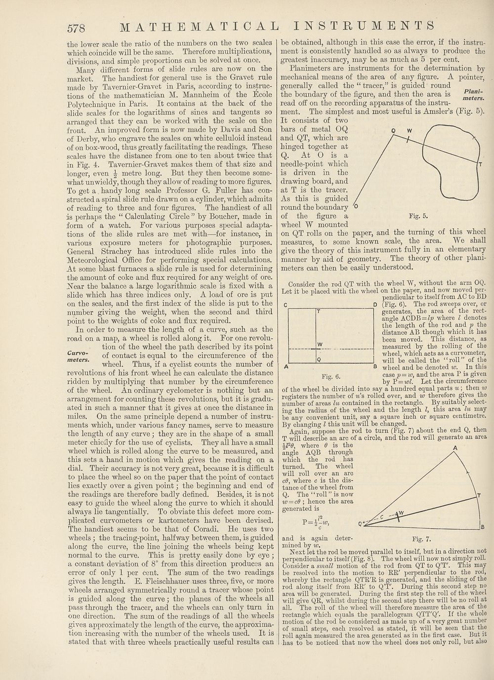
Planimeters are instruments for the determination by
mechanical means of the area of any figure. A pointer,
generally called the “ tracer,” is guided round
the boundary of the figure, and then the area is Plan!-
read off on the recording apparatus of the instru¬
ment. The simplest and most useful is Amsler’s (Fig. 5).
It consists of two
bars of metal OQ
and QT, which are
hinged together at
Q. At O is a
needle-point which
is driven in the
drawing board, and
at T is the tracer.
As this is guided
round the boundary
of the figure a Fig. 5.
wheel W mounted
on QT rolls on the paper, and the turning of this wheel
measures, to some known scale, the area. We shall
give the theory of this instrument fully in an elementary
manner by aid of geometry. The theory of other plani¬
meters can then be easily understood.
Fig. 6.
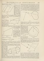
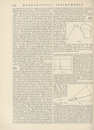
Consider the rod QT with the wheel W, without the arm OQ.
Let it be placed with the wheel on the paper, and now moved per¬
pendicular to itself from AC to BD
C D (Fig. 6). The rod sweeps over, or
generates, the area of the rect¬
angle ACDB = Zp where l denotes
the length of the rod aud p the
distance AB though which it has
been moved. This distance, as
measured by the rolling of the
wheel, which acts as a curvometer,
will be called the “roll” of the
wheel and be denoted w. In this
case p— w, and the area P is given
by Y — wl. Let the circumference
of the wheel be divided into say a hundred equal parts u ; then w
registers the number of w’s rolled over, and w therefore gives the
number of areas lu contained in the rectangle. By suitably select¬
ing the radius of the wheel and the length l, this area lu may
be any convenient unit, say a square inch or square centimetre.
By changing l this unit will be changed.
Again, suppose the rod to turn (Fig. 7) about the end Q, then
T will describe an arc of a circle, and the rod will generate an area
where 6 is the
angle AQB through
which the rod has
turned. The wheel
will roll over an arc
cO, where c is the dis¬
tance of the wheel from
Q. The ‘1 roll ” is now
io = cO ; hence the area
generated is
72
P = F-M,)
and is again deter- Fig. 7,
mined by w.
Next let the rod be moved parallel to itself, but in a direction not
perpendicular to itself (Fig. 8). The wheel will now not simply roll.
Consider a small motion of the rod from QT to Q'T'. This may
be resolved into the motion to RR' perpendicular to the rod,
whereby the rectangle QTR'R is generated, and the sliding of the
rod along itself from RR' to Q'T'. During this second step no
area will be generated. During the first step the roll of the wheel
will give QR, whilst during the second step there will be no roll at
all. The roll of the wheel will therefore measure the area of the
rectangle which equals the parallelogram QTT'Q'. If the whole
motion of the rod be considered as made up of a very great number
of small steps, each resolved as stated, it will be seen that the
roll again measured the area generated as in the first case. But it
has to be noticed that now the wheel does not only roll, but also
the lower scale the ratio of the numbers on the two scales
which coincide will be the same. Therefore multiplications,
divisions, and simple proportions can be solved at once.
Many different forms of slide rules are now on the
market. The handiest for general use is the Gravet rule
made by Tavernier-Gravet in Paris, according to instruc¬
tions of the mathematician M. Mannheim of the Ecole
Polytechnique in Paris. It contains at the back of the
slide scales for the logarithms of sines and tangents so
arranged that they can be worked with the scale on the
front. An improved form is now made by Davis and Son
of Derby, who engrave the scales on white celluloid instead
of on box-wood, thus greatly facilitating the readings. These
scales have the distance from one to ten about twice that
in Fig. 4. Tavernier-Gravet makes them of that size and
longer, even | metre long. But they then become some¬
what unwieldy, though they allow of reading to more figures.
To get a handy long scale Professor G. Fuller has con¬
structed a spiral slide rule drawn on a cylinder, which admits
of reading to three and four figures. The handiest of all
is perhaps the “ Calculating Circle ” by Boucher, made in
form of a watch. For various purposes special adapta¬
tions of the slide rules are met with—for instance, in
various exposure meters for photographic purposes.
General Strachey has introduced slide rules into the
Meteorological Office for performing special calculations.
At some blast furnaces a slide rule is used for determining
the amount of coke and flux required for any weight of ore.
Xear the balance a large logarithmic scale is fixed with a
slide which has three indices only. A load of ore is put
on the scales, and the first index of the slide is put to the
number giving the weight, when the second and third
point to the weights of coke and flux required.
In order to measure the length of a curve, such as the
road on a map, a wheel is rolled along it. For one revolu¬
tion of the wheel the path described by its point
Curve- 0f contact is equal to the circumference of the
meters, x
wheel. Thus, if a cyclist counts the number of
revolutions of his front wheel he can calculate the distance
ridden by multiplying that number by the circumference
of the wheel. An ordinary cyclometer is nothing but an
arrangement for counting these revolutions, but it is gradu¬
ated in such a manner that it gives at once the distance in
miles. On the same principle depend a number of instru¬
ments which, under various fancy names, serve to measure
the length of any curve; they are in the shape of a small
meter chiefly for the use of cyclists. They all have a small
wheel which is rolled along the curve to be measured, and
this sets a hand in motion which gives the reading on a
dial. Their accuracy is not very great, because it is difficult
to place the wheel so on the paper that the point of contact
lies exactly over a given point; the beginning and end of
the readings are therefore badly defined. Besides, it is not
easy to guide the wheel along the curve to which it should
always lie tangentially. To obviate this defect more com¬
plicated curvometers or kartometers have been devised.
The handiest seems to be that of Coradi. He uses two
wheels ; the tracing-point, halfway between them, is guided
along the curve, the line joining the wheels being kept
normal to the curve. This is pretty easily done by eye ;
a constant deviation of 8° from this direction produces an
error of only 1 per cent. The sum of the two readings
gives the length. E. Fleischhauer uses three, five, or more
wheels arranged symmetrically round a tracer whose point
is guided along the curve; the planes of the wheels all
pass through the tracer, and the wheels can only turn in
one direction. The sum of the readings of all the wheels
gives approximately the length of the curve, the approxima¬
tion increasing with the number of the wheels used. It is
stated that with three wheels practically useful results can
be obtained, although in this case the error, if the instru¬
ment is consistently handled so as always to produce the
greatest inaccuracy, may be as much as 5 per cent.
Planimeters are instruments for the determination by
mechanical means of the area of any figure. A pointer,
generally called the “ tracer,” is guided round
the boundary of the figure, and then the area is Plan!-
read off on the recording apparatus of the instru¬
ment. The simplest and most useful is Amsler’s (Fig. 5).
It consists of two
bars of metal OQ
and QT, which are
hinged together at
Q. At O is a
needle-point which
is driven in the
drawing board, and
at T is the tracer.
As this is guided
round the boundary
of the figure a Fig. 5.
wheel W mounted
on QT rolls on the paper, and the turning of this wheel
measures, to some known scale, the area. We shall
give the theory of this instrument fully in an elementary
manner by aid of geometry. The theory of other plani¬
meters can then be easily understood.
Fig. 6.
Consider the rod QT with the wheel W, without the arm OQ.
Let it be placed with the wheel on the paper, and now moved per¬
pendicular to itself from AC to BD
C D (Fig. 6). The rod sweeps over, or
generates, the area of the rect¬
angle ACDB = Zp where l denotes
the length of the rod aud p the
distance AB though which it has
been moved. This distance, as
measured by the rolling of the
wheel, which acts as a curvometer,
will be called the “roll” of the
wheel and be denoted w. In this
case p— w, and the area P is given
by Y — wl. Let the circumference
of the wheel be divided into say a hundred equal parts u ; then w
registers the number of w’s rolled over, and w therefore gives the
number of areas lu contained in the rectangle. By suitably select¬
ing the radius of the wheel and the length l, this area lu may
be any convenient unit, say a square inch or square centimetre.
By changing l this unit will be changed.
Again, suppose the rod to turn (Fig. 7) about the end Q, then
T will describe an arc of a circle, and the rod will generate an area
where 6 is the
angle AQB through
which the rod has
turned. The wheel
will roll over an arc
cO, where c is the dis¬
tance of the wheel from
Q. The ‘1 roll ” is now
io = cO ; hence the area
generated is
72
P = F-M,)
and is again deter- Fig. 7,
mined by w.
Next let the rod be moved parallel to itself, but in a direction not
perpendicular to itself (Fig. 8). The wheel will now not simply roll.
Consider a small motion of the rod from QT to Q'T'. This may
be resolved into the motion to RR' perpendicular to the rod,
whereby the rectangle QTR'R is generated, and the sliding of the
rod along itself from RR' to Q'T'. During this second step no
area will be generated. During the first step the roll of the wheel
will give QR, whilst during the second step there will be no roll at
all. The roll of the wheel will therefore measure the area of the
rectangle which equals the parallelogram QTT'Q'. If the whole
motion of the rod be considered as made up of a very great number
of small steps, each resolved as stated, it will be seen that the
roll again measured the area generated as in the first case. But it
has to be noticed that now the wheel does not only roll, but also
Set display mode to:
![]() Universal Viewer |
Universal Viewer | ![]() Mirador |
Large image | Transcription
Mirador |
Large image | Transcription
Images and transcriptions on this page, including medium image downloads, may be used under the Creative Commons Attribution 4.0 International Licence unless otherwise stated. ![]()
| Encyclopaedia Britannica > New volumes of the Encyclopædia Britannica > Volume 30, K-MOR > (612) Page 578 |
|---|
| Permanent URL | https://digital.nls.uk/193575457 |
|---|
| Attribution and copyright: |
|
|---|---|
| Shelfmark | EB.18 |
|---|---|
| Description | Ten editions of 'Encyclopaedia Britannica', issued from 1768-1903, in 231 volumes. Originally issued in 100 weekly parts (3 volumes) between 1768 and 1771 by publishers: Colin Macfarquhar and Andrew Bell (Edinburgh); editor: William Smellie: engraver: Andrew Bell. Expanded editions in the 19th century featured more volumes and contributions from leading experts in their fields. Managed and published in Edinburgh up to the 9th edition (25 volumes, from 1875-1889); the 10th edition (1902-1903) re-issued the 9th edition, with 11 supplementary volumes. |
|---|---|
| Additional NLS resources: |
|