New volumes of the Encyclopædia Britannica > Volume 30, K-MOR
(609) Page 575 - Mathematical instruments
Download files
Complete book:
Individual page:
Thumbnail gallery: Grid view | List view
575
MATHEMATICAL INSTRUMENTS.
Fig. 1.
Calculating machines, designed for the
mechanical performance of numerical calculations,
have in modern times come into ever-increasing
Calculating use_ They may be classified as follows (i.)
Addition machines; the first invented by
Pascal (1642). (ii.) Addition machines modified to
facilitate multiplication; the first by Leibnitz (1671).
(iii.) True multiplication machines; Leon Bolles (1888),
Steiger (1894). (iv.) Difference machines; Muller (1786),
Babbage (1822). (v.) Analytical machines; Babbage
(1834). The number of distinct machines of the first three
kinds is remarkable and is being constantly added to, old
machines being improved and new ones invented ; Professor
R. Mehmke has counted over eighty distinct machines of
this type. The fullest published account of the subject is
given by Mehmke in the Encyclopaedic der Mathematischen
Wissenschaften, article “Numerisches Rechnen,” vol. i.,
heft 6 (1901). It contains historical notes and full
references. Dyck’s Catalogue also contains descriptions of
various machines. We will confine ourselves to explaining
the principles of some leading types,
without giving an exact description
of any particular one.
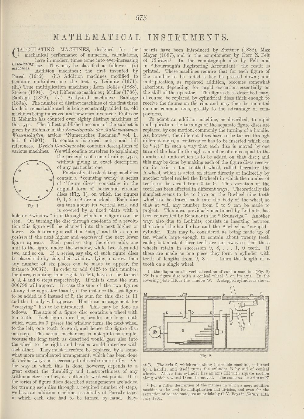
Practically all calculating machines
contain a “counting work,” a series
of “ figure discs ” consisting in the
original form of horizontal circular
discs (Fig. 1), on which the figures
0, 1, 2 to 9 are marked. Each disc
can turn about its vertical axis, and
is covered by a fixed plate with a
hole or “ window ” in it through which one figure can be
seen. On turning the disc through one-tenth of a revolu¬
tion this figure will be changed into the next higher or
lower. Such turning is called a “ step,” and this step is
positive if the next higher and negative if the next lower
figure appears. Each positive step therefore adds one
unit to the figure under the window, while two steps add
two, and so on. If a series, say six, of such figure discs
be placed side by side, their windows lying in a row, then
any number of six places can be made to appear, for
instance 000373. In order to add 6425 to this number,
the discs, counting from right to left, have to be turned
5, 2, 4 and 6 steps respectively. If this is done the sum
006798 will appear. In case the sum of the two figures
at any disc is greater than 9, if for instance the last figure
to be added is 8 instead of 5, the sum for this disc is 11
and the 1 only will appear. Hence an arrangement for
“ carrying ” has to be introduced. This may be done as
follows. The axis of a figure disc contains a wheel with
ten teeth. Each figure disc has, besides one long tooth
which when its 0 passes the window turns the next wheel
to the left, one tooth forward, and hence the figure disc
one step. The actual mechanism is not quite so simple,
because the long teeth as described would gear also into
the wheel to the right, and besides would interfere with
each other. They must therefore be replaced by a some¬
what more complicated arrangement, which has been done
in various ways not necessary to describe more fully. On
the way in which this is done, however, depends to a
great extent the durability and trustworthiness of any
arithmometer ; in fact, it is often its weakest point. If to
the series of figure discs described arrangements are added
for turning each disc through a required number of steps,
we have an addition machine, essentially of Pascal’s type,
in which each disc had to be turned by hand. Key¬
boards have been introduced by Stettner (1882), Max
Mayer (1887), and in the comptometer by Dorr Z. Felt
of Chicago.1 In the comptograph also by Felt and
in “Bourrough’s Registering Accountant” the result is
printed. These machines require that for each figure of
the number to be added a key be pressed down; and
multiplication, as repeated addition, becomes somewhat
laborious, depending for rapid execution essentially on
the skill of the operator. The figure discs described may,
of course, be replaced by cylindrical discs thick enough to
receive the figures on the rim, and may then be mounted
on one common axis, greatly to the advantage of com¬
pactness.
To adapt an addition machine, as described, to rapid
multiplication the turnings of the separate figure discs are
replaced by one motion, commonly the turning of a handle.
As, however, the different discs have to be turned through
different steps, a contrivance has to be inserted which can
be “ set ” in such a way that each disc is moved by one
turn of the handle through a number of steps equal to the
number of units which is to be added on that disc; and
this may be done by making each of the figure discs receive
on its axis a ten-toothed wheel, called hereafter the
A-wheel, which is acted on either directly or indirectly by
another wheel (called the B-wheel) in which the number of
teeth can be varied from 0 to 9. This variation of the
teeth has been effected in different ways. Theoretically the
simplest seems to be to have on the B-wheel nine teeth
which can be drawn back into the body of the wheel, so
that at will any number from 0 to 9 can be made to
project. This idea, previously mentioned by Leibnitz, has
been reinvented by Bohdner in the “ Brunsviga.” Another
way, also due to Leibnitz, consists in inserting between
the axis of the handle bar and the A-wheel a “ stepped ”
cylinder. This may be considered as being made up of
ten wheels large enough to contain about twenty teeth
each; but most of these teeth are cut away so that these
wheels retain in succession 9, 8, . . . 1, 0 teeth. If
these are made as one piece they form a cylinder with
teeth of lengths from 9, 8 . . . times the length of a
tooth on a single wheel.
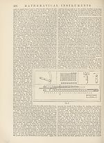
In the diagrammatic vertical section of such a machine (Fig. 2)
FF is a figure disc with a conical -wheel A on its axis. In the
covering plate HK is the window W. A stepped cylinder is shown
at B. The axis Z, which runs along the whole machine, is turned
by a handle, and itself turns the cylinder B by aid of conical
wheels. Above this cylinder lies an axis EE with square section
along which a wheel D can be moved. The same axis carries at E'
1 For a fuller description of the manner in which a mere addition
machine can be used for multiplication and division, and even for the
extraction of square roots, see an article by C. V. Boys in Nature, 11th
July 1901.
MATHEMATICAL INSTRUMENTS.
Fig. 1.
Calculating machines, designed for the
mechanical performance of numerical calculations,
have in modern times come into ever-increasing
Calculating use_ They may be classified as follows (i.)
Addition machines; the first invented by
Pascal (1642). (ii.) Addition machines modified to
facilitate multiplication; the first by Leibnitz (1671).
(iii.) True multiplication machines; Leon Bolles (1888),
Steiger (1894). (iv.) Difference machines; Muller (1786),
Babbage (1822). (v.) Analytical machines; Babbage
(1834). The number of distinct machines of the first three
kinds is remarkable and is being constantly added to, old
machines being improved and new ones invented ; Professor
R. Mehmke has counted over eighty distinct machines of
this type. The fullest published account of the subject is
given by Mehmke in the Encyclopaedic der Mathematischen
Wissenschaften, article “Numerisches Rechnen,” vol. i.,
heft 6 (1901). It contains historical notes and full
references. Dyck’s Catalogue also contains descriptions of
various machines. We will confine ourselves to explaining
the principles of some leading types,
without giving an exact description
of any particular one.
Practically all calculating machines
contain a “counting work,” a series
of “ figure discs ” consisting in the
original form of horizontal circular
discs (Fig. 1), on which the figures
0, 1, 2 to 9 are marked. Each disc
can turn about its vertical axis, and
is covered by a fixed plate with a
hole or “ window ” in it through which one figure can be
seen. On turning the disc through one-tenth of a revolu¬
tion this figure will be changed into the next higher or
lower. Such turning is called a “ step,” and this step is
positive if the next higher and negative if the next lower
figure appears. Each positive step therefore adds one
unit to the figure under the window, while two steps add
two, and so on. If a series, say six, of such figure discs
be placed side by side, their windows lying in a row, then
any number of six places can be made to appear, for
instance 000373. In order to add 6425 to this number,
the discs, counting from right to left, have to be turned
5, 2, 4 and 6 steps respectively. If this is done the sum
006798 will appear. In case the sum of the two figures
at any disc is greater than 9, if for instance the last figure
to be added is 8 instead of 5, the sum for this disc is 11
and the 1 only will appear. Hence an arrangement for
“ carrying ” has to be introduced. This may be done as
follows. The axis of a figure disc contains a wheel with
ten teeth. Each figure disc has, besides one long tooth
which when its 0 passes the window turns the next wheel
to the left, one tooth forward, and hence the figure disc
one step. The actual mechanism is not quite so simple,
because the long teeth as described would gear also into
the wheel to the right, and besides would interfere with
each other. They must therefore be replaced by a some¬
what more complicated arrangement, which has been done
in various ways not necessary to describe more fully. On
the way in which this is done, however, depends to a
great extent the durability and trustworthiness of any
arithmometer ; in fact, it is often its weakest point. If to
the series of figure discs described arrangements are added
for turning each disc through a required number of steps,
we have an addition machine, essentially of Pascal’s type,
in which each disc had to be turned by hand. Key¬
boards have been introduced by Stettner (1882), Max
Mayer (1887), and in the comptometer by Dorr Z. Felt
of Chicago.1 In the comptograph also by Felt and
in “Bourrough’s Registering Accountant” the result is
printed. These machines require that for each figure of
the number to be added a key be pressed down; and
multiplication, as repeated addition, becomes somewhat
laborious, depending for rapid execution essentially on
the skill of the operator. The figure discs described may,
of course, be replaced by cylindrical discs thick enough to
receive the figures on the rim, and may then be mounted
on one common axis, greatly to the advantage of com¬
pactness.
To adapt an addition machine, as described, to rapid
multiplication the turnings of the separate figure discs are
replaced by one motion, commonly the turning of a handle.
As, however, the different discs have to be turned through
different steps, a contrivance has to be inserted which can
be “ set ” in such a way that each disc is moved by one
turn of the handle through a number of steps equal to the
number of units which is to be added on that disc; and
this may be done by making each of the figure discs receive
on its axis a ten-toothed wheel, called hereafter the
A-wheel, which is acted on either directly or indirectly by
another wheel (called the B-wheel) in which the number of
teeth can be varied from 0 to 9. This variation of the
teeth has been effected in different ways. Theoretically the
simplest seems to be to have on the B-wheel nine teeth
which can be drawn back into the body of the wheel, so
that at will any number from 0 to 9 can be made to
project. This idea, previously mentioned by Leibnitz, has
been reinvented by Bohdner in the “ Brunsviga.” Another
way, also due to Leibnitz, consists in inserting between
the axis of the handle bar and the A-wheel a “ stepped ”
cylinder. This may be considered as being made up of
ten wheels large enough to contain about twenty teeth
each; but most of these teeth are cut away so that these
wheels retain in succession 9, 8, . . . 1, 0 teeth. If
these are made as one piece they form a cylinder with
teeth of lengths from 9, 8 . . . times the length of a
tooth on a single wheel.
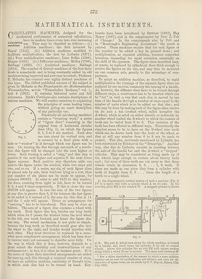
In the diagrammatic vertical section of such a machine (Fig. 2)
FF is a figure disc with a conical -wheel A on its axis. In the
covering plate HK is the window W. A stepped cylinder is shown
at B. The axis Z, which runs along the whole machine, is turned
by a handle, and itself turns the cylinder B by aid of conical
wheels. Above this cylinder lies an axis EE with square section
along which a wheel D can be moved. The same axis carries at E'
1 For a fuller description of the manner in which a mere addition
machine can be used for multiplication and division, and even for the
extraction of square roots, see an article by C. V. Boys in Nature, 11th
July 1901.
Set display mode to:
![]() Universal Viewer |
Universal Viewer | ![]() Mirador |
Large image | Transcription
Mirador |
Large image | Transcription
Images and transcriptions on this page, including medium image downloads, may be used under the Creative Commons Attribution 4.0 International Licence unless otherwise stated. ![]()
| Encyclopaedia Britannica > New volumes of the Encyclopædia Britannica > Volume 30, K-MOR > (609) Page 575 - Mathematical instruments |
|---|
| Permanent URL | https://digital.nls.uk/193575418 |
|---|
| Attribution and copyright: |
|
|---|---|
| Shelfmark | EB.18 |
|---|---|
| Description | Ten editions of 'Encyclopaedia Britannica', issued from 1768-1903, in 231 volumes. Originally issued in 100 weekly parts (3 volumes) between 1768 and 1771 by publishers: Colin Macfarquhar and Andrew Bell (Edinburgh); editor: William Smellie: engraver: Andrew Bell. Expanded editions in the 19th century featured more volumes and contributions from leading experts in their fields. Managed and published in Edinburgh up to the 9th edition (25 volumes, from 1875-1889); the 10th edition (1902-1903) re-issued the 9th edition, with 11 supplementary volumes. |
|---|---|
| Additional NLS resources: |
|