New volumes of the Encyclopædia Britannica > Volume 30, K-MOR
(468) Page 438
Download files
Complete book:
Individual page:
Thumbnail gallery: Grid view | List view
MAGNETISM
438
apparatus of a similar type devised by Kapp {Journ. Inst. Elec.
Eng. vol. xxiii. p. 199) differs only in a few details from Thompson’s
permeameter. Ewing has described an arrangement in which the
test bar has a soft-iron pole piece clamped to each of its ends ; the
pole pieces are joined by a long well-fitting block of iron, which is
placed upon them (like the “keeper” of a magnet), and the in¬
duction is measured by the force required to detach the block. In
all such measurements a correction should be made in respect of
the demagnetizing force due to the joint, and unless the lit is very
accurate the demagnetizing action will be variable. In the mag¬
netic balance of du Bois {Magnetic Circuit, p. 346) the uncertainty
arising from the presence of a joint is avoided, the force measured
being that exerted between two pieces of iron separated from
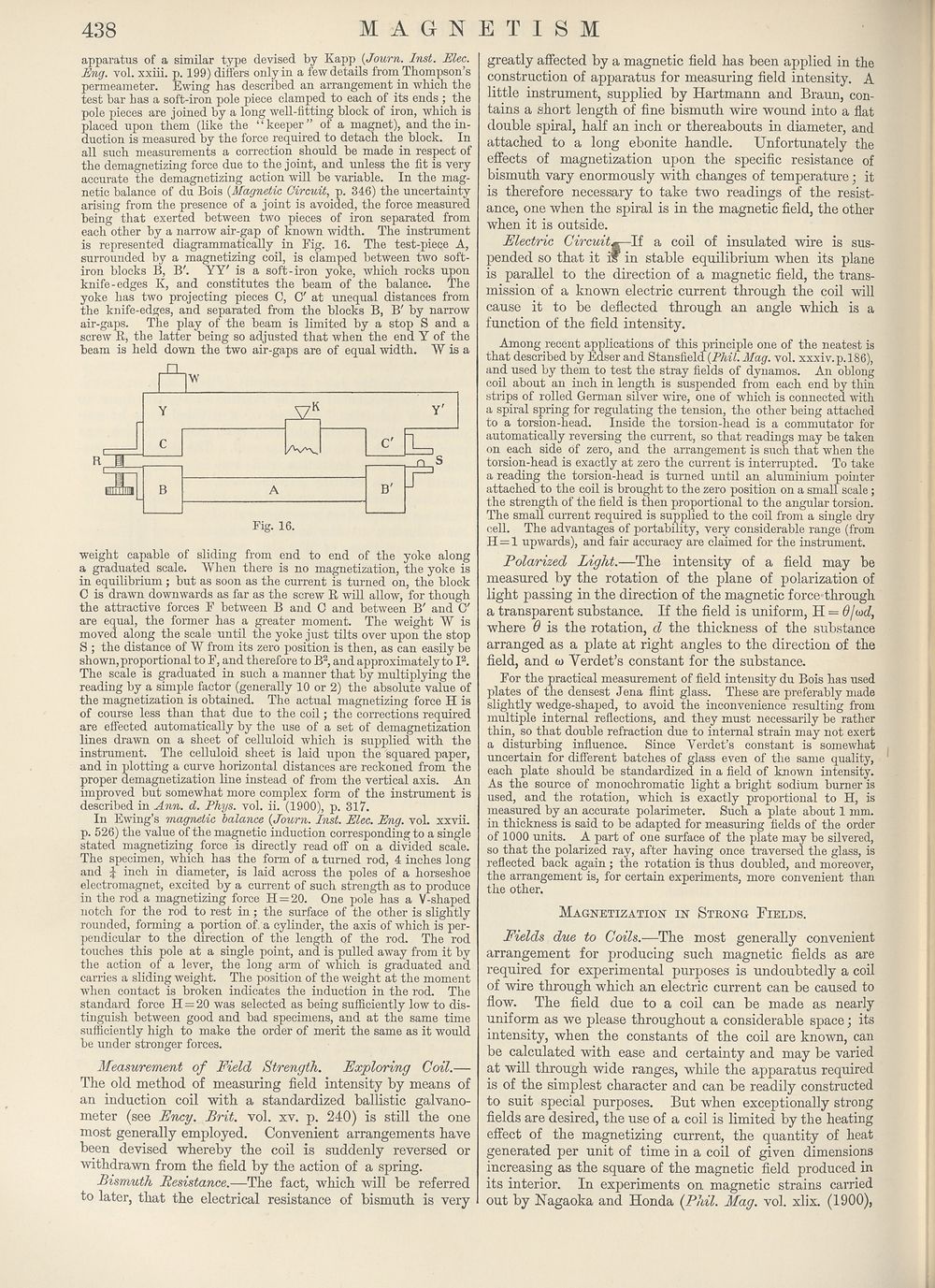
each other by a narrow air-gap of known width. The instrument
is represented diagrammatically in Fig. 16. The test-piece A,
surrounded by a magnetizing coil, is clamped between two soft-
iron blocks B, B'. YY' is a soft-iron yoke, which rocks upon
knife-edges K, and constitutes the beam of the balance. The
yoke has two projecting pieces 0, O' at unequal distances from
the knife-edges, and separated from the blocks B, B' by narrow
air-gaps. The play of the beam is limited by a stop S and a
screw R, the latter being so adjusted that when the end Y of the
beam is held down the two air-gaps are of equal width. W is a
weight capable of sliding from end to end of the yoke along
a graduated scale. When there is no magnetization, the yoke is
in equilibrium; but as soon as the current is turned on, the block
C is drawn downwards as far as the screw R will allow, for though
the attractive forces F between B and C and between Br and O'
are equal, the former has a greater moment. The weight W is
moved along the scale until the yoke just tilts over upon the stop
S ; the distance of W from its zero position is then, as can easily be
shown, proportional to F, and therefore to B2, and approximately to I2.
The scale is graduated in such a manner that by multiplying the
reading by a simple factor (generally 10 or 2) the absolute’value of
the magnetization is obtained. The actual magnetizing force H is
of course less than that due to the coil; the corrections required
are effected automatically by the use of a set of demagnetization
lines drawn on a sheet of celluloid which is supplied with the
instrument. The celluloid sheet is laid upon the squared paper,
and in plotting a curve horizontal distances are reckoned from the
proper demagnetization line instead of from the vertical axis. An
improved but somewhat more complex form of the instrument is
described in Ann. d. Phys. vol. ii. (1900), p. 317.
In Ewing’s magnetic balance {Journ. Inst. Elec. Eng. vol. xxvii.
p. 526) the value of the magnetic induction corresponding to a single
stated magnetizing force is directly read off on a divided scale.
The specimen, which has the form of a turned rod, 4 inches long
and jr inch in diameter, is laid across the poles of a horseshoe
electromagnet, excited by a current of such strength as to produce
in the rod a magnetizing force 11 = 20. One pole has a V-shaped
notch for the rod to rest in; the surface of the other is slightly
rounded, forming a portion of a cylinder, the axis of which is per¬
pendicular to the direction of the length of the rod. The rod
touches this pole at a single point, and is pulled away from it by
the action of a lever, the long arm of which is graduated and
carries a sliding weight. The position of the weight at the moment
when contact is broken indicates the induction in the rod. The
standard force H = 20 was selected as being sufficiently low to dis¬
tinguish between good and bad specimens, and at the same time
sufficiently high to make the order of merit the same as it would
be under stronger forces.
Measurement of Field Strength. Exploring Coil.—
The old method of measuring field intensity by means of
an induction coil with a standardized ballistic galvano¬
meter (see Ency. Brit. vol. xv. p. 240) is still the one
most generally employed. Convenient arrangements have
been devised whereby the coil is suddenly reversed or
withdrawn from the field by the action of a spring.
Bismuth Resistance.—The fact, which will be referred
to later, that the electrical resistance of bismuth is very
greatly affected by a magnetic field has been applied in the
construction of apparatus for measuring field intensity. A
little instrument, supplied by Hartmann and Braun, con¬
tains a short length of fine bismuth wire wound into a flat
double spiral, half an inch or thereabouts in diameter, and
attached to a long ebonite handle. Unfortunately the
effects of magnetization upon the specific resistance of
bismuth vary enormously with changes of temperature; it
is therefore necessary to take two readings of the resist¬
ance, one when the spiral is in the magnetic field, the other
when it is outside.
Electric Circuit^~\{ a coil of insulated wire is sus¬
pended so that it i® in stable equilibrium when its plane
is parallel to the direction of a magnetic field, the trans¬
mission of a known electric current through the coil will
cause it to be deflected through an angle which is a
function of the field intensity.
Among recent applications of this principle one of the neatest is
that described by Edser and Stansfield {Phil. Mag. vol. xxxiv.p.186),
and used by them to test the stray fields of dynamos. An oblong
coil about an inch in length is suspended from each end by thin
strips of rolled German silver wire, one of which is connected with
a spiral spring for regulating the tension, the other being attached
to a torsion-head. Inside the torsion-head is a commutator for
automatically reversing the current, so that readings may be taken
on each side of zero, and the arrangement is such that when the
torsion-head is exactly at zero the current is interrupted. To take
a reading the torsion-head is turned until an aluminium pointer
attached to the coil is brought to the zero position on a small scale ;
the strength of the field is then proportional to the angular torsion.
The small current required is supplied to the coil from a single dry
cell. The advantages of portability, very considerable range (from
H = 1 upwards), and fair accuracy are claimed for the instrument.
Polarized Light.—The intensity of a field may be
measured by the rotation of the plane of polarization of
light passing in the direction of the magnetic force through
a transparent substance. If the field is uniform, H = d/W,
where 6 is the rotation, d the thickness of the substance
arranged as a plate at right angles to the direction of the
field, and w Yerdet’s constant for the substance.
For the practical measurement of field intensity du Bois has used
plates of the densest Jena flint glass. These are preferably made
slightly wedge-shaped, to avoid the inconvenience resulting from
multiple internal reflections, and they must necessarily be rather
thin, so that double refraction due to internal strain may not exert
a disturbing influence. Since Yerdet’s constant is somewhat
uncertain for different batches of glass even of the same quality,
each plate should be standardized in a field of known intensity.
As the source of monochromatic light a bright sodium burner is
used, and the rotation, which is exactly proportional to H, is
measured by an accurate polarimeter. Such a plate about 1 mm.
in thickness is said to be adapted for measuring fields of the order
of 1000 units. A part of one surface of the plate may be silvered,
so that the polarized ray, after having once traversed the glass, is
reflected back again ; the rotation is thus doubled, and moreover,
the arrangement is, for certain experiments, more convenient than
the other.
Magnetization in Strong Fields.
Fields due to Coils.—The most generally convenient
arrangement for producing such magnetic fields as are
required for experimental purposes is undoubtedly a coil
of wire through which an electric current can be caused to
flow. The field due to a coil can be made as nearly
uniform as we please throughout a considerable space; its
intensity, when the constants of the coil are known, can
be calculated with ease and certainty and may be varied
at will through wide ranges, while the apparatus required
is of the simplest character and can be readily constructed
to suit special purposes. But when exceptionally strong
fields are desired, the use of a coil is limited by the heating
effect of the magnetizing current, the quantity of heat
generated per unit of time in a coil of given dimensions
increasing as the square of the magnetic field produced in
its interior. In experiments on magnetic strains carried
out by Nagaoka and Honda (Phil. Mag. vol. xlix. (1900),
438
apparatus of a similar type devised by Kapp {Journ. Inst. Elec.
Eng. vol. xxiii. p. 199) differs only in a few details from Thompson’s
permeameter. Ewing has described an arrangement in which the
test bar has a soft-iron pole piece clamped to each of its ends ; the
pole pieces are joined by a long well-fitting block of iron, which is
placed upon them (like the “keeper” of a magnet), and the in¬
duction is measured by the force required to detach the block. In
all such measurements a correction should be made in respect of
the demagnetizing force due to the joint, and unless the lit is very
accurate the demagnetizing action will be variable. In the mag¬
netic balance of du Bois {Magnetic Circuit, p. 346) the uncertainty
arising from the presence of a joint is avoided, the force measured
being that exerted between two pieces of iron separated from
each other by a narrow air-gap of known width. The instrument
is represented diagrammatically in Fig. 16. The test-piece A,
surrounded by a magnetizing coil, is clamped between two soft-
iron blocks B, B'. YY' is a soft-iron yoke, which rocks upon
knife-edges K, and constitutes the beam of the balance. The
yoke has two projecting pieces 0, O' at unequal distances from
the knife-edges, and separated from the blocks B, B' by narrow
air-gaps. The play of the beam is limited by a stop S and a
screw R, the latter being so adjusted that when the end Y of the
beam is held down the two air-gaps are of equal width. W is a
weight capable of sliding from end to end of the yoke along
a graduated scale. When there is no magnetization, the yoke is
in equilibrium; but as soon as the current is turned on, the block
C is drawn downwards as far as the screw R will allow, for though
the attractive forces F between B and C and between Br and O'
are equal, the former has a greater moment. The weight W is
moved along the scale until the yoke just tilts over upon the stop
S ; the distance of W from its zero position is then, as can easily be
shown, proportional to F, and therefore to B2, and approximately to I2.
The scale is graduated in such a manner that by multiplying the
reading by a simple factor (generally 10 or 2) the absolute’value of
the magnetization is obtained. The actual magnetizing force H is
of course less than that due to the coil; the corrections required
are effected automatically by the use of a set of demagnetization
lines drawn on a sheet of celluloid which is supplied with the
instrument. The celluloid sheet is laid upon the squared paper,
and in plotting a curve horizontal distances are reckoned from the
proper demagnetization line instead of from the vertical axis. An
improved but somewhat more complex form of the instrument is
described in Ann. d. Phys. vol. ii. (1900), p. 317.
In Ewing’s magnetic balance {Journ. Inst. Elec. Eng. vol. xxvii.
p. 526) the value of the magnetic induction corresponding to a single
stated magnetizing force is directly read off on a divided scale.
The specimen, which has the form of a turned rod, 4 inches long
and jr inch in diameter, is laid across the poles of a horseshoe
electromagnet, excited by a current of such strength as to produce
in the rod a magnetizing force 11 = 20. One pole has a V-shaped
notch for the rod to rest in; the surface of the other is slightly
rounded, forming a portion of a cylinder, the axis of which is per¬
pendicular to the direction of the length of the rod. The rod
touches this pole at a single point, and is pulled away from it by
the action of a lever, the long arm of which is graduated and
carries a sliding weight. The position of the weight at the moment
when contact is broken indicates the induction in the rod. The
standard force H = 20 was selected as being sufficiently low to dis¬
tinguish between good and bad specimens, and at the same time
sufficiently high to make the order of merit the same as it would
be under stronger forces.
Measurement of Field Strength. Exploring Coil.—
The old method of measuring field intensity by means of
an induction coil with a standardized ballistic galvano¬
meter (see Ency. Brit. vol. xv. p. 240) is still the one
most generally employed. Convenient arrangements have
been devised whereby the coil is suddenly reversed or
withdrawn from the field by the action of a spring.
Bismuth Resistance.—The fact, which will be referred
to later, that the electrical resistance of bismuth is very
greatly affected by a magnetic field has been applied in the
construction of apparatus for measuring field intensity. A
little instrument, supplied by Hartmann and Braun, con¬
tains a short length of fine bismuth wire wound into a flat
double spiral, half an inch or thereabouts in diameter, and
attached to a long ebonite handle. Unfortunately the
effects of magnetization upon the specific resistance of
bismuth vary enormously with changes of temperature; it
is therefore necessary to take two readings of the resist¬
ance, one when the spiral is in the magnetic field, the other
when it is outside.
Electric Circuit^~\{ a coil of insulated wire is sus¬
pended so that it i® in stable equilibrium when its plane
is parallel to the direction of a magnetic field, the trans¬
mission of a known electric current through the coil will
cause it to be deflected through an angle which is a
function of the field intensity.
Among recent applications of this principle one of the neatest is
that described by Edser and Stansfield {Phil. Mag. vol. xxxiv.p.186),
and used by them to test the stray fields of dynamos. An oblong
coil about an inch in length is suspended from each end by thin
strips of rolled German silver wire, one of which is connected with
a spiral spring for regulating the tension, the other being attached
to a torsion-head. Inside the torsion-head is a commutator for
automatically reversing the current, so that readings may be taken
on each side of zero, and the arrangement is such that when the
torsion-head is exactly at zero the current is interrupted. To take
a reading the torsion-head is turned until an aluminium pointer
attached to the coil is brought to the zero position on a small scale ;
the strength of the field is then proportional to the angular torsion.
The small current required is supplied to the coil from a single dry
cell. The advantages of portability, very considerable range (from
H = 1 upwards), and fair accuracy are claimed for the instrument.
Polarized Light.—The intensity of a field may be
measured by the rotation of the plane of polarization of
light passing in the direction of the magnetic force through
a transparent substance. If the field is uniform, H = d/W,
where 6 is the rotation, d the thickness of the substance
arranged as a plate at right angles to the direction of the
field, and w Yerdet’s constant for the substance.
For the practical measurement of field intensity du Bois has used
plates of the densest Jena flint glass. These are preferably made
slightly wedge-shaped, to avoid the inconvenience resulting from
multiple internal reflections, and they must necessarily be rather
thin, so that double refraction due to internal strain may not exert
a disturbing influence. Since Yerdet’s constant is somewhat
uncertain for different batches of glass even of the same quality,
each plate should be standardized in a field of known intensity.
As the source of monochromatic light a bright sodium burner is
used, and the rotation, which is exactly proportional to H, is
measured by an accurate polarimeter. Such a plate about 1 mm.
in thickness is said to be adapted for measuring fields of the order
of 1000 units. A part of one surface of the plate may be silvered,
so that the polarized ray, after having once traversed the glass, is
reflected back again ; the rotation is thus doubled, and moreover,
the arrangement is, for certain experiments, more convenient than
the other.
Magnetization in Strong Fields.
Fields due to Coils.—The most generally convenient
arrangement for producing such magnetic fields as are
required for experimental purposes is undoubtedly a coil
of wire through which an electric current can be caused to
flow. The field due to a coil can be made as nearly
uniform as we please throughout a considerable space; its
intensity, when the constants of the coil are known, can
be calculated with ease and certainty and may be varied
at will through wide ranges, while the apparatus required
is of the simplest character and can be readily constructed
to suit special purposes. But when exceptionally strong
fields are desired, the use of a coil is limited by the heating
effect of the magnetizing current, the quantity of heat
generated per unit of time in a coil of given dimensions
increasing as the square of the magnetic field produced in
its interior. In experiments on magnetic strains carried
out by Nagaoka and Honda (Phil. Mag. vol. xlix. (1900),
Set display mode to:
![]() Universal Viewer |
Universal Viewer | ![]() Mirador |
Large image | Transcription
Mirador |
Large image | Transcription
Images and transcriptions on this page, including medium image downloads, may be used under the Creative Commons Attribution 4.0 International Licence unless otherwise stated. ![]()
| Encyclopaedia Britannica > New volumes of the Encyclopædia Britannica > Volume 30, K-MOR > (468) Page 438 |
|---|
| Permanent URL | https://digital.nls.uk/193573585 |
|---|
| Attribution and copyright: |
|
|---|---|
| Shelfmark | EB.18 |
|---|---|
| Description | Ten editions of 'Encyclopaedia Britannica', issued from 1768-1903, in 231 volumes. Originally issued in 100 weekly parts (3 volumes) between 1768 and 1771 by publishers: Colin Macfarquhar and Andrew Bell (Edinburgh); editor: William Smellie: engraver: Andrew Bell. Expanded editions in the 19th century featured more volumes and contributions from leading experts in their fields. Managed and published in Edinburgh up to the 9th edition (25 volumes, from 1875-1889); the 10th edition (1902-1903) re-issued the 9th edition, with 11 supplementary volumes. |
|---|---|
| Additional NLS resources: |
|