New volumes of the Encyclopædia Britannica > Volume 30, K-MOR
(466) Page 436
Download files
Complete book:
Individual page:
Thumbnail gallery: Grid view | List view
MAGNETISM
436
differ from and resemble one another as regards their
magnetic properties. Curves of magnetization (which
express the relation of I to H) have a close resemblance
to those of induction; and indeed, since B = H + 47tI, and
47tI (except in extreme fields) greatly exceeds H in numerical
value, we may generally, without serious error, put I = B/47T,
and transform curves of induction into curves of magnetiza¬
tion by merely altering the scale to which the ordinates
are referred. A scale for the approximate transformation
for the curves in Fig. 12 is given at the right-hand side of
the diagram, the greatest error introduced by neglecting
H/47T not exceeding 0‘6 per cent. A study of such curves
as these reveals the fact that there are three distinct
stages in the process of magnetization. During the first
stage, when the magnetizing force is small, the magnet¬
ization (or the induction) increases rather slowly with
increasing force; this is well shown by the nickel curve
in the diagram, but the effect would be no less con¬
spicuous in the iron curve if the abscissae were plotted to
a larger scale. During the second stage small increments
of magnetizing force are attended by relatively large incre¬
ments of magnetization, as is indicated by the steep
ascent of the curve. Then the curve bends over, forming
what is often called a “knee,” and a third stage is entered
upon, during which a considerable increase of magnetizing
force has little further effect upon the magnetization.
When in this condition the metal is popularly said to be
“ saturated.” Under increasing magnetizing forces, greatly
exceeding those comprised within the limits of the diagram,
the magnetization does practically reach a limit, the
maximum value being attained with a magnetizing force
of less than 2000 for wrought iron and nickel, and less
than 4000 for cast iron and cobalt. The induction, how¬
ever, continues to increase indefinitely, though very slowly.
These observations have an important bearing upon the
molecular theory of magnetism, which will be referred
to later.
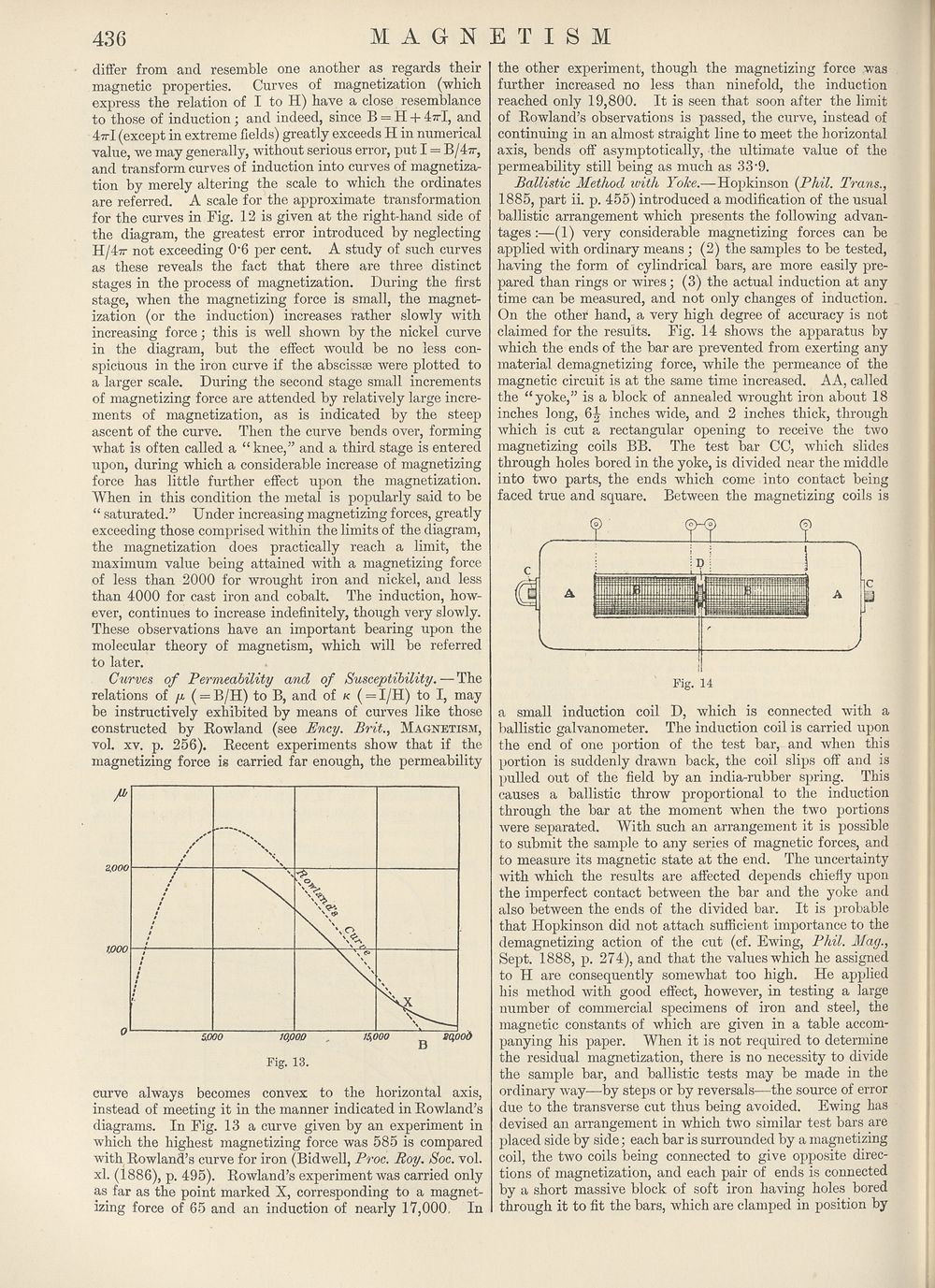
Curves of Permeability and of Susceptibility.—The
relations of y ( = B/H) to B, and of k ( = I/H) to I, may
be instructively exhibited by means of curves like those
constructed by Rowland (see Ency. Brit., Magnetism,
vol. xv. p. 256). Recent experiments show that if the
magnetizing force is carried far enough, the permeability
curve always becomes convex to the horizontal axis,
instead of meeting it in the manner indicated in Rowland’s
diagrams. In Fig. 13 a curve given by an experiment in
which the highest magnetizing force was 585 is compared
with Rowland’s curve for iron (Bidwell, Proc. Roy. Soc. vol.
xl. (1886), p. 495). Rowland’s experiment was carried only
as far as the point marked X, corresponding to a magnet¬
izing force of 65 and an induction of nearly 17,000, In
the other experiment, though the magnetizing force was
further increased no less than ninefold, the induction
reached only 19,800. It is seen that soon after the limit
of Rowland’s observations is passed, the curve, instead of
continuing in an almost straight line to meet the horizontal
axis, bends off asymptotically, the ultimate value of the
permeability still being as much as OS'O.
Ballistic Method ivith Yoke.—Hopkinson {Phil. Trans.,
1885, part ii. p. 455) introduced a modification of the usual
ballistic arrangement which presents the following advan¬
tages :—(1) very considerable magnetizing forces can be
applied with ordinary means ; (2) the samples to be tested,
having the form of cylindrical bars, are more easily pre¬
pared than rings or wires; (3) the actual induction at any
time can be measured, and not only changes of induction.
On the other hand, a very high degree of accuracy is not
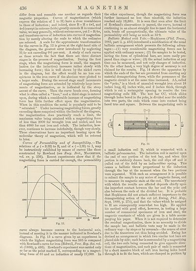
claimed for the results. Fig. 14 shows the apparatus by
which the ends of the bar are prevented from exerting any
material demagnetizing force, while the permeance of the
magnetic circuit is at the same time increased. AA, called
the “yoke,” is a block of annealed wrought iron about 18
inches long, 6^ inches wide, and 2 inches thick, through
which is cut a rectangular opening to receive the two
magnetizing coils BB. The test bar CC, which slides
through holes bored in the yoke, is divided near the middle
into two parts, the ends which come into contact being
faced true and square. Between the magnetizing coils is
a small induction coil D, which is connected with a
ballistic galvanometer. The induction coil is carried upon
the end of one portion of the test bar, and when this
portion is suddenly drawn back, the coil slips off and is
pulled out of the field by an india-rubber spring. This
causes a ballistic throw proportional to the induction
through the bar at the moment when the two portions
were separated. With such an arrangement it is possible
to submit the sample to any series of magnetic forces, and
to measure its magnetic state at the end. The uncertainty
with which the results are affected depends chieffy upon
the imperfect contact between the bar and the yoke and
also between the ends of the divided bar. It is probable
that Hopkinson did not attach sufficient importance to the
demagnetizing action of the cut (cf. Ewing, Phil. May.,
Sept. 1888, p. 274), and that the values which he assigned
to H are consequently somewhat too high. He applied
his method with good effect, however, in testing a large
number of commercial specimens of iron and steel, the
magnetic constants of which are given in a table accom¬
panying his paper. When it is not required to determine
the residual magnetization, there is no necessity to divide
the sample bar, and ballistic tests may be made in the
ordinary way—by steps or by reversals—the source of error
due to the transverse cut thus being avoided. Ewing has
devised an arrangement in which two similar test bars are
placed side by side; each bar is surrounded by a magnetizing
coil, the two coils being connected to give opposite direc¬
tions of magnetization, and each pair of ends is connected
by a short massive block of soft iron having holes bored
through it to fit the bars, which are clamped in position by
436
differ from and resemble one another as regards their
magnetic properties. Curves of magnetization (which
express the relation of I to H) have a close resemblance
to those of induction; and indeed, since B = H + 47tI, and
47tI (except in extreme fields) greatly exceeds H in numerical
value, we may generally, without serious error, put I = B/47T,
and transform curves of induction into curves of magnetiza¬
tion by merely altering the scale to which the ordinates
are referred. A scale for the approximate transformation
for the curves in Fig. 12 is given at the right-hand side of
the diagram, the greatest error introduced by neglecting
H/47T not exceeding 0‘6 per cent. A study of such curves
as these reveals the fact that there are three distinct
stages in the process of magnetization. During the first
stage, when the magnetizing force is small, the magnet¬
ization (or the induction) increases rather slowly with
increasing force; this is well shown by the nickel curve
in the diagram, but the effect would be no less con¬
spicuous in the iron curve if the abscissae were plotted to
a larger scale. During the second stage small increments
of magnetizing force are attended by relatively large incre¬
ments of magnetization, as is indicated by the steep
ascent of the curve. Then the curve bends over, forming
what is often called a “knee,” and a third stage is entered
upon, during which a considerable increase of magnetizing
force has little further effect upon the magnetization.
When in this condition the metal is popularly said to be
“ saturated.” Under increasing magnetizing forces, greatly
exceeding those comprised within the limits of the diagram,
the magnetization does practically reach a limit, the
maximum value being attained with a magnetizing force
of less than 2000 for wrought iron and nickel, and less
than 4000 for cast iron and cobalt. The induction, how¬
ever, continues to increase indefinitely, though very slowly.
These observations have an important bearing upon the
molecular theory of magnetism, which will be referred
to later.
Curves of Permeability and of Susceptibility.—The
relations of y ( = B/H) to B, and of k ( = I/H) to I, may
be instructively exhibited by means of curves like those
constructed by Rowland (see Ency. Brit., Magnetism,
vol. xv. p. 256). Recent experiments show that if the
magnetizing force is carried far enough, the permeability
curve always becomes convex to the horizontal axis,
instead of meeting it in the manner indicated in Rowland’s
diagrams. In Fig. 13 a curve given by an experiment in
which the highest magnetizing force was 585 is compared
with Rowland’s curve for iron (Bidwell, Proc. Roy. Soc. vol.
xl. (1886), p. 495). Rowland’s experiment was carried only
as far as the point marked X, corresponding to a magnet¬
izing force of 65 and an induction of nearly 17,000, In
the other experiment, though the magnetizing force was
further increased no less than ninefold, the induction
reached only 19,800. It is seen that soon after the limit
of Rowland’s observations is passed, the curve, instead of
continuing in an almost straight line to meet the horizontal
axis, bends off asymptotically, the ultimate value of the
permeability still being as much as OS'O.
Ballistic Method ivith Yoke.—Hopkinson {Phil. Trans.,
1885, part ii. p. 455) introduced a modification of the usual
ballistic arrangement which presents the following advan¬
tages :—(1) very considerable magnetizing forces can be
applied with ordinary means ; (2) the samples to be tested,
having the form of cylindrical bars, are more easily pre¬
pared than rings or wires; (3) the actual induction at any
time can be measured, and not only changes of induction.
On the other hand, a very high degree of accuracy is not
claimed for the results. Fig. 14 shows the apparatus by
which the ends of the bar are prevented from exerting any
material demagnetizing force, while the permeance of the
magnetic circuit is at the same time increased. AA, called
the “yoke,” is a block of annealed wrought iron about 18
inches long, 6^ inches wide, and 2 inches thick, through
which is cut a rectangular opening to receive the two
magnetizing coils BB. The test bar CC, which slides
through holes bored in the yoke, is divided near the middle
into two parts, the ends which come into contact being
faced true and square. Between the magnetizing coils is
a small induction coil D, which is connected with a
ballistic galvanometer. The induction coil is carried upon
the end of one portion of the test bar, and when this
portion is suddenly drawn back, the coil slips off and is
pulled out of the field by an india-rubber spring. This
causes a ballistic throw proportional to the induction
through the bar at the moment when the two portions
were separated. With such an arrangement it is possible
to submit the sample to any series of magnetic forces, and
to measure its magnetic state at the end. The uncertainty
with which the results are affected depends chieffy upon
the imperfect contact between the bar and the yoke and
also between the ends of the divided bar. It is probable
that Hopkinson did not attach sufficient importance to the
demagnetizing action of the cut (cf. Ewing, Phil. May.,
Sept. 1888, p. 274), and that the values which he assigned
to H are consequently somewhat too high. He applied
his method with good effect, however, in testing a large
number of commercial specimens of iron and steel, the
magnetic constants of which are given in a table accom¬
panying his paper. When it is not required to determine
the residual magnetization, there is no necessity to divide
the sample bar, and ballistic tests may be made in the
ordinary way—by steps or by reversals—the source of error
due to the transverse cut thus being avoided. Ewing has
devised an arrangement in which two similar test bars are
placed side by side; each bar is surrounded by a magnetizing
coil, the two coils being connected to give opposite direc¬
tions of magnetization, and each pair of ends is connected
by a short massive block of soft iron having holes bored
through it to fit the bars, which are clamped in position by
Set display mode to:
![]() Universal Viewer |
Universal Viewer | ![]() Mirador |
Large image | Transcription
Mirador |
Large image | Transcription
Images and transcriptions on this page, including medium image downloads, may be used under the Creative Commons Attribution 4.0 International Licence unless otherwise stated. ![]()
| Encyclopaedia Britannica > New volumes of the Encyclopædia Britannica > Volume 30, K-MOR > (466) Page 436 |
|---|
| Permanent URL | https://digital.nls.uk/193573559 |
|---|
| Attribution and copyright: |
|
|---|---|
| Shelfmark | EB.18 |
|---|---|
| Description | Ten editions of 'Encyclopaedia Britannica', issued from 1768-1903, in 231 volumes. Originally issued in 100 weekly parts (3 volumes) between 1768 and 1771 by publishers: Colin Macfarquhar and Andrew Bell (Edinburgh); editor: William Smellie: engraver: Andrew Bell. Expanded editions in the 19th century featured more volumes and contributions from leading experts in their fields. Managed and published in Edinburgh up to the 9th edition (25 volumes, from 1875-1889); the 10th edition (1902-1903) re-issued the 9th edition, with 11 supplementary volumes. |
|---|---|
| Additional NLS resources: |
|