New volumes of the Encyclopædia Britannica > Volume 30, K-MOR
(461) Page 431
Download files
Complete book:
Individual page:
Thumbnail gallery: Grid view | List view
431
MAGNETISM
the ratio of the length of the ellipsoid 2c to its equatorial diameter
2a ( = c/a), the dimensional ratio, denoted by the symbol nu
Since
the above expression for N may be written
N
_ 471- /
~nt2- 1\
log
m+ Am'-1 -1
2 ^/m2 -1 m - v/nv* -1
47T
/-
V
log ( m + Vtn2 -
from which the value of N for a given dimensional ratio can be
calculated. When the ellipsoid is so much elongated that 1 is
negligible in relation to m2, the expression approximates to the
simpler form
N=S(los2m~l)‘
The demagnetizing force inside a cylindrical rod placed longi¬
tudinally in a uniform field H0 is not uniform, being greatest at
the ends and least in the middle part. Denoting its mean value
by Hi, and that of the demagnetizing factor by N, we have
H=Ho-Hi=H0-NL
Du Bois has shown that when the dimensional ratio m (=length/
diameter) exceeds 100, Nm2 = constant=45, and hence for long
thin rods
N = 45/m2.
From an analysis of a number of experiments made with rods
of dilferent dimensions, du Bois has deduced the corresponding
mean demagnetizing factors. These, together with values of m2N
for cylindrical rods, and of H and m2N for ellipsoids of revolution,
are given in the following very useful table {loc. cit. p. 41):—
Demagnetizing Factors.
Cylinder.
N.
nt2N.
Ellipsoid.
N.
m-X.
0
0-5
1
5
10
15
20
25
30
40
50
60
70
80
90
100
150
200
300
400
500
1000
12-5664
0-2160
0-1206
0-0775
0-0533
0-0393
0-0238
0-0162
0-0118
0-0089
0-0069
0-0055
0-0045
0-0020
0-0011
0-00050
0-00028
0-00018
0-00005
21-6
27-1
31-0
33-4
35-4
38-7
40-5
42- 4
43- 7
44- 4
44- 8
45- 0
45-0
45-0
45-0
45-0
45-0
45-0
12-5664
6-5864
4-1888
07015
0-2549
0-1350
0-0848
0-0579
0-0432
0-0266
0-0181
0-0132
0-0101
0-0080
0-0065
0-0054
0-0026
0-0016
0-00075
0-00045
0-00030
0-00008
25-5
30-5
34-0
36-2
38*8
42-5
45-3
47-5
49-5
51- 2
52- 5
54-0
58-3
64-0
67-5
72-0
75-0
80-0
In the middle part of a rod which has a length of 400 or 500
diameters the effect of the ends is insensible ; but for many
experiments the condition of endlessness may be best secured by
giving the metal the shape of a ring of uniform section, the
magnetic field being produced by an electric current through a
coil of wire evenly wound round the ring. In such cases Hj = 0
and H = H0.
The residual magnetization Ir retained by a bar of ferromag¬
netic metal after it has been removed from the influence of an
external field produces a demagnetizing force NI„ which is greater
the smaller the dimensional ratio. Hence the difficulty of im¬
parting any considerable permanent magnetization to a short
thick bar not possessed of great coercive force. The magnet¬
ization retained by a long thin rod, even when its coercive force
is small, is sometimes little less than that which was produced
by the direct action of the field.
Demagnetization by Reversals.—In tne course of an experiment
it is often desired to eliminate the effects of previous magnetiza¬
tion, and, as far as possible, wipe out the magnetic history of a
specimen. In order to attain this result it was formerly the
practice to raise the metal to a bright red heat, and allow it to
cool while carefully guarded from magnetic influence. This
operation, besides being very troublesome, was open to the objec¬
tion that it was almost sure to produce a material but uncertain
change in the physical constitution of the metal, so that, in fact,
the results of experiments made before and after the treatment
were not comparable. Ewing introduced the method (Phil.
Trans, vol. clxxvi. p. 539) of demagnetizing a specimen by subject¬
ing it to a succession of magnetic forces which alternated in
direction and gradually diminished in strength from a high value
to zero. By means of a simple arrangement, which will be
described farther on, this process can be carried out in a few
seconds, and the metal can be brought as often as desired to a
definite condition, which, if not quite identical with the virgin
state, at least closely approximates to it.
The laws of the magnetic circuit are discussed under the heading
Electromagnet.
Magnetic Measurements.
Measurement of Magnetization and Induction.—The
magnetic condition assumed by a piece of ferromagnetic
metal in different circumstances is determinable by various
modes of experiment which may be classed as magneto¬
metric, ballistic, and traction methods. When either the
magnetization I or the induction B corresponding to a
given magnetizing force H is known, the other may be
found by means of the formula B = 47tI + H.
Magnetometric Methods.—Intensity of magnetization is
most directly measured by observing the action which a
magnetized body, generally a long straight rod, exerts
upon a small magnetic needle placed near it. The mag¬
netic needle may be cemented horizontally across the back
of a little plane or concave mirror, about ^ or § inch in
diameter, which is suspended by a single fibre of unspun
silk; this arrangement, when enclosed in a case with a
glazed front to protect it from currents of air, constitutes
a simple but efficient magnetometer. Deflections of the
suspended needle are indicated by the movement of a
narrow beam of light which the mirror reflects from a lamp
and focusses upon a graduated cardboard scale placed at a
distance of a few feet; the angular deflection of the beam
of light is, of course, twice that of the needle. The sus¬
pended needle is, in the absence of disturbing causes,
directed solely by the horizontal component of the earth’s
field of magnetic force HE, and therefore sets itself
approximately north and south. The magnetized body
which is to be tested should be placed in such a position
that the force Hp due to its poles may, at the spot
occupied by the suspended needle, act in a direction at
right angles to that due to the earth—that is, east and
west. The direction of the resultant field of force will
then make, with that of HE, an angle 9, such that HP/HK =
tan 6, and the suspended needle will be deflected through
the same angle. We have therefore
H =H tan 6.
P E
The angle 6 is indicated by the position of the spot of
light upon the scale, and the horizontal intensity of the
earth’s field HE is known; thus we can at once determine
the value of Hp, from which the magnetization I of the
body under test may be calculated.
In order to fulfil the requirement that the field which a mag¬
netized rod produces at the magnetometer shall be at right angles
to that of the earth, the rod may be conveniently placed in any
one of three different positions with regard to the suspended
needle.
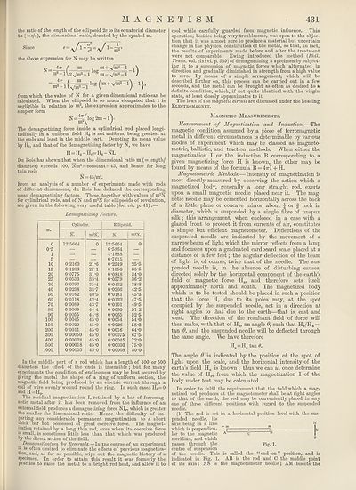
(1) The rod is set in a horizontal position level with the sus¬
pended needle, its
axis being in a line _ ^
which is perpendicu- p ; ) JL
lar to the magnetic A c B
meridian, and which s
passes through the pig. 1.
centre of suspension
of the needle. This is called the “end-on” position, and is
indicated in Fig. 1. AB is the rod and C the middle point
of its axis; NS is the magnetometer needle ; AM bisects the
MAGNETISM
the ratio of the length of the ellipsoid 2c to its equatorial diameter
2a ( = c/a), the dimensional ratio, denoted by the symbol nu
Since
the above expression for N may be written
N
_ 471- /
~nt2- 1\
log
m+ Am'-1 -1
2 ^/m2 -1 m - v/nv* -1
47T
/-
V
log ( m + Vtn2 -
from which the value of N for a given dimensional ratio can be
calculated. When the ellipsoid is so much elongated that 1 is
negligible in relation to m2, the expression approximates to the
simpler form
N=S(los2m~l)‘
The demagnetizing force inside a cylindrical rod placed longi¬
tudinally in a uniform field H0 is not uniform, being greatest at
the ends and least in the middle part. Denoting its mean value
by Hi, and that of the demagnetizing factor by N, we have
H=Ho-Hi=H0-NL
Du Bois has shown that when the dimensional ratio m (=length/
diameter) exceeds 100, Nm2 = constant=45, and hence for long
thin rods
N = 45/m2.
From an analysis of a number of experiments made with rods
of dilferent dimensions, du Bois has deduced the corresponding
mean demagnetizing factors. These, together with values of m2N
for cylindrical rods, and of H and m2N for ellipsoids of revolution,
are given in the following very useful table {loc. cit. p. 41):—
Demagnetizing Factors.
Cylinder.
N.
nt2N.
Ellipsoid.
N.
m-X.
0
0-5
1
5
10
15
20
25
30
40
50
60
70
80
90
100
150
200
300
400
500
1000
12-5664
0-2160
0-1206
0-0775
0-0533
0-0393
0-0238
0-0162
0-0118
0-0089
0-0069
0-0055
0-0045
0-0020
0-0011
0-00050
0-00028
0-00018
0-00005
21-6
27-1
31-0
33-4
35-4
38-7
40-5
42- 4
43- 7
44- 4
44- 8
45- 0
45-0
45-0
45-0
45-0
45-0
45-0
12-5664
6-5864
4-1888
07015
0-2549
0-1350
0-0848
0-0579
0-0432
0-0266
0-0181
0-0132
0-0101
0-0080
0-0065
0-0054
0-0026
0-0016
0-00075
0-00045
0-00030
0-00008
25-5
30-5
34-0
36-2
38*8
42-5
45-3
47-5
49-5
51- 2
52- 5
54-0
58-3
64-0
67-5
72-0
75-0
80-0
In the middle part of a rod which has a length of 400 or 500
diameters the effect of the ends is insensible ; but for many
experiments the condition of endlessness may be best secured by
giving the metal the shape of a ring of uniform section, the
magnetic field being produced by an electric current through a
coil of wire evenly wound round the ring. In such cases Hj = 0
and H = H0.
The residual magnetization Ir retained by a bar of ferromag¬
netic metal after it has been removed from the influence of an
external field produces a demagnetizing force NI„ which is greater
the smaller the dimensional ratio. Hence the difficulty of im¬
parting any considerable permanent magnetization to a short
thick bar not possessed of great coercive force. The magnet¬
ization retained by a long thin rod, even when its coercive force
is small, is sometimes little less than that which was produced
by the direct action of the field.
Demagnetization by Reversals.—In tne course of an experiment
it is often desired to eliminate the effects of previous magnetiza¬
tion, and, as far as possible, wipe out the magnetic history of a
specimen. In order to attain this result it was formerly the
practice to raise the metal to a bright red heat, and allow it to
cool while carefully guarded from magnetic influence. This
operation, besides being very troublesome, was open to the objec¬
tion that it was almost sure to produce a material but uncertain
change in the physical constitution of the metal, so that, in fact,
the results of experiments made before and after the treatment
were not comparable. Ewing introduced the method (Phil.
Trans, vol. clxxvi. p. 539) of demagnetizing a specimen by subject¬
ing it to a succession of magnetic forces which alternated in
direction and gradually diminished in strength from a high value
to zero. By means of a simple arrangement, which will be
described farther on, this process can be carried out in a few
seconds, and the metal can be brought as often as desired to a
definite condition, which, if not quite identical with the virgin
state, at least closely approximates to it.
The laws of the magnetic circuit are discussed under the heading
Electromagnet.
Magnetic Measurements.
Measurement of Magnetization and Induction.—The
magnetic condition assumed by a piece of ferromagnetic
metal in different circumstances is determinable by various
modes of experiment which may be classed as magneto¬
metric, ballistic, and traction methods. When either the
magnetization I or the induction B corresponding to a
given magnetizing force H is known, the other may be
found by means of the formula B = 47tI + H.
Magnetometric Methods.—Intensity of magnetization is
most directly measured by observing the action which a
magnetized body, generally a long straight rod, exerts
upon a small magnetic needle placed near it. The mag¬
netic needle may be cemented horizontally across the back
of a little plane or concave mirror, about ^ or § inch in
diameter, which is suspended by a single fibre of unspun
silk; this arrangement, when enclosed in a case with a
glazed front to protect it from currents of air, constitutes
a simple but efficient magnetometer. Deflections of the
suspended needle are indicated by the movement of a
narrow beam of light which the mirror reflects from a lamp
and focusses upon a graduated cardboard scale placed at a
distance of a few feet; the angular deflection of the beam
of light is, of course, twice that of the needle. The sus¬
pended needle is, in the absence of disturbing causes,
directed solely by the horizontal component of the earth’s
field of magnetic force HE, and therefore sets itself
approximately north and south. The magnetized body
which is to be tested should be placed in such a position
that the force Hp due to its poles may, at the spot
occupied by the suspended needle, act in a direction at
right angles to that due to the earth—that is, east and
west. The direction of the resultant field of force will
then make, with that of HE, an angle 9, such that HP/HK =
tan 6, and the suspended needle will be deflected through
the same angle. We have therefore
H =H tan 6.
P E
The angle 6 is indicated by the position of the spot of
light upon the scale, and the horizontal intensity of the
earth’s field HE is known; thus we can at once determine
the value of Hp, from which the magnetization I of the
body under test may be calculated.
In order to fulfil the requirement that the field which a mag¬
netized rod produces at the magnetometer shall be at right angles
to that of the earth, the rod may be conveniently placed in any
one of three different positions with regard to the suspended
needle.
(1) The rod is set in a horizontal position level with the sus¬
pended needle, its
axis being in a line _ ^
which is perpendicu- p ; ) JL
lar to the magnetic A c B
meridian, and which s
passes through the pig. 1.
centre of suspension
of the needle. This is called the “end-on” position, and is
indicated in Fig. 1. AB is the rod and C the middle point
of its axis; NS is the magnetometer needle ; AM bisects the
Set display mode to:
![]() Universal Viewer |
Universal Viewer | ![]() Mirador |
Large image | Transcription
Mirador |
Large image | Transcription
Images and transcriptions on this page, including medium image downloads, may be used under the Creative Commons Attribution 4.0 International Licence unless otherwise stated. ![]()
| Encyclopaedia Britannica > New volumes of the Encyclopædia Britannica > Volume 30, K-MOR > (461) Page 431 |
|---|
| Permanent URL | https://digital.nls.uk/193573494 |
|---|
| Attribution and copyright: |
|
|---|---|
| Shelfmark | EB.18 |
|---|---|
| Description | Ten editions of 'Encyclopaedia Britannica', issued from 1768-1903, in 231 volumes. Originally issued in 100 weekly parts (3 volumes) between 1768 and 1771 by publishers: Colin Macfarquhar and Andrew Bell (Edinburgh); editor: William Smellie: engraver: Andrew Bell. Expanded editions in the 19th century featured more volumes and contributions from leading experts in their fields. Managed and published in Edinburgh up to the 9th edition (25 volumes, from 1875-1889); the 10th edition (1902-1903) re-issued the 9th edition, with 11 supplementary volumes. |
|---|---|
| Additional NLS resources: |
|