Encyclopaedia Britannica > Volume 8, DIA-England
(667) Page 657
Download files
Complete book:
Individual page:
Thumbnail gallery: Grid view | List view

ELECTRICITY.
657
lectrical and Dr Hare informs us that it is exceedingly sensible,
yaratus-and that it has enabled him to detect the electricity pro-
''V'’-' duced by one contact between a copper and zinc disc,
each six inches in diameter.
Henley's Quadrant Electrometer.
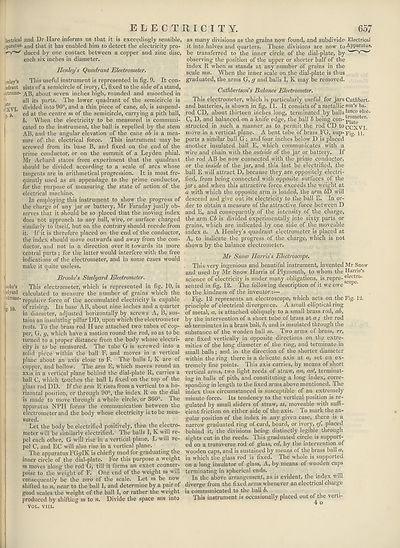
mley’s This useful instrument is represented in fig. 9. It con-
adrant sists of a semicircle of ivory, C, fixed to the side of a stand,
(Ctrome- about seven inches high, rounded and smoothed in
1 ■ all its parts. The lower quadrant of the semicircle is
i'XVI divided into 90°, and a thin piece of cane, ab, is suspend-
,"y, ’ ed at the centre m of the semicircle, carrying a pith ball,
b. When the electricity to be measured is communi¬
cated to the instrument, the ball is repelled by the stem
AB, and the angular elevation of the cane ab is a mea¬
sure of the electrical force. This instrument may be
screwed from its base B, and fixed on the end of the
prime conductor, or on the summit of a Leyden phial.
Mr Achard states from experiment that the quadrant
should be divided according to a scale of arcs whose
tangents are in arithmetical progression. It is most fre¬
quently used as an appendage to the prime conductor,
for the purpose of measuring the state of action of the
electrical machine.
In employing this instrument to show the progress of
the charge of any jar or battery, Mr Faraday justly ob¬
serves that it should be so placed that the moving index
does not approach to any ball, wire, or surface charged
similarly to itself, but on the contrary should recede from
it. If it is therefore placed on the end of the conductor,
the index should move outwards and away from the con¬
ductor, and not in a direction over it towards its more
central parts ; for the latter would interfere with the free
indications of the electrometer, and in some cases would
make it quite useless.
Brooke's Steelyard Electrometer.
ooke’s This electrometer, which is represented in fig, 10, is
dyanl calculated to measure the number of grains which the
ltrome'repulsive force of the accumulated electricity is capable
1q of raising. Its base AB, about nine inches and a quarter
in diameter, adjusted horizontally by screws A, B, sus¬
tains an insulating pillar DD, upon which the electrometer
rests. To the brass rod H are attached two tubes of cop¬
per, G, g, which have a motion round the rod, so as to be
turned to a proper distance from the body whose electri¬
city is to be measured. The tube G is screwed into a
solid piece within the ball F, and moves in a vertical
plane about an axis close to F. The balls I, K are of
copper, and hollow. The arm E, which moves round an
axis in a vertical plane behind the dial-plate It, carries a
ball C, which touches the ball L fixed on the top of the
glass rod DD. If the arm E rises from a vertical to a ho¬
rizontal position, or through 90°, the index It on the dial
is made to move through a whole circle, or 360°. Ihe
apparatus NPH forms the communication between the
electrometer and the body whose electricity is to be mea¬
sured.
Let the body be electrified positively, then the electro¬
meter will be similarly electrified. The balls I, K will re¬
pel each other, G will rise in a vertical plane, L will re¬
pel C, and EC will also rise in a vertical plane.
The apparatus FG^IK is chiefly used for graduating the
inner circle of the dial-plate. For this purpose a weight
m moves along the rod G, till it forms an exact counter¬
poise to the weight of F. One end of the weight m will
consequently be the zero of the scale. Let m be now
shifted to near to the ball I, and determine by a pair of
good scales the weight of the ball I, or rather the weight
produced by shifting m to n. Divide the space mn into
VOL. vm.
as many divisions as the grains now found, and subdivide Electrical
it into halves and quarters. These divisions are now to ^PParatus-
be transferred to the inner circle of the dial-plate, by
observing the position of the upper or shorter half of the
index R when m stands at any number of grains in the
scale mn. When the inner scale on the dial-plate is thus
graduated, the arms G, g and balls I, K may be removed.
Cuihbertsons Balance Electrometer.
This electrometer, which is particularly useful for jars Cuthbert-
and batteries, is shown in fig. 11. It consists of a metallic son’s ba-
rod CD, about thirteen inches long, terminated by balls ^aTlce elec-
C, D, and balanced on a knife edge, the ball b being con-pj°™eeter*
structed in such a manner as to permit the rod CD to^xvi
move in a vertical plane. A bent tube of brass FG, sup-pig. n.
ports a similar ball G; and four inches below D is placed
another insulated ball E, which communicates with a
wire and chain with the outside of the jar or battery. If
the rod AB be now connected with the prime conductor,
or the inside of the jar, and this last be electrified, the
ball E will attract D, because they are oppositely electri¬
fied, from being connected with opposite surfaces of the
jar; and when this attractive force exceeds the weight at
a with which the opposite arm is loaded, the arm &D will
descend and give out its electricity to the ball E. In or¬
der to obtain a measure of the attractive force between D
and E, and consequently of the intensity of the charge,
the arm Cb is divided experimentally into sixty parts or
grains, which are indicated by one side of the moveable
index a. A Henley’s quadrant electrometer is placed at
A, to indicate the progress of the charge, which is not
shown by the balance electrometer.
Mr Snow Harris's Electroscope.
This very ingenious and beautiful instrument, invented Mr Snow
and used by Mr Snow Harris of Plymouth, to whom the Harris’s
science of electricity is under many obligations, is repre-electro'
sented in fig. 12. The following description of it weowe‘scope‘
to the kindness of the inventor:—
Fig. 12 represents an electroscope, which acts on the Fig. 12.
principle of electrical divergence. A small elliptical ring
of metal, a, is attached obliquely to a small brass rod, ab,
by the intervention of a short tube of brass at a; the rod
ab terminates in a brass ball, b, and is insulated through the
substance of the wooden ball m. Two arms of brass, rr,
are fixed vertically in opposite directions on the extre¬
mities of the long diameter of the ring, and terminate in
small balls; and in the direction of tbe shorter diameter
within the ring there is a delicate axis at a, set on ex¬
tremely fine points. This axis carries, by means of short
vertical arms, two light reeds of straw, an, an', terminat¬
ing in balls of pith, and constituting a long index, corre¬
sponding in length to the fixed arms above mentioned. The
index thus circumstanced is susceptible of an extremely
minute force. Its tendency to the vertical position is re¬
gulated by small sliders of straw, ss, moveable with suffi¬
cient friction on either side of the axis. To mark the an¬
gular position of the index in any given case, there is a
narrow graduated ring of card, board, or ivory, ef, placed
behind it, the divisions being distinctly legible through
sights cut in the reeds. This graduated circle is support¬
ed on a transverse rod of glass, cd, by the intervention of
wooden caps, and is sustained by means of the brass ball a,
in which the glass rod is fixed. The whole is supported
on a long insulator of glass, A, by means of wooden caps
terminating in spherical ends.
In the above arrangement, as is evident, the index will
diverge from the fixed arms whenever an electrical charge
is communicated to the ball b.
This instrument is occasionally placed out of the verti-
4 o
Set display mode to:
![]() Universal Viewer |
Universal Viewer | ![]() Mirador |
Large image | Transcription
Mirador |
Large image | Transcription
Images and transcriptions on this page, including medium image downloads, may be used under the Creative Commons Attribution 4.0 International Licence unless otherwise stated. ![]()
| Encyclopaedia Britannica > Encyclopaedia Britannica > Volume 8, DIA-England > (667) Page 657 |
|---|
| Permanent URL | https://digital.nls.uk/193331676 |
|---|
| Attribution and copyright: |
|
|---|
| Description | Ten editions of 'Encyclopaedia Britannica', issued from 1768-1903, in 231 volumes. Originally issued in 100 weekly parts (3 volumes) between 1768 and 1771 by publishers: Colin Macfarquhar and Andrew Bell (Edinburgh); editor: William Smellie: engraver: Andrew Bell. Expanded editions in the 19th century featured more volumes and contributions from leading experts in their fields. Managed and published in Edinburgh up to the 9th edition (25 volumes, from 1875-1889); the 10th edition (1902-1903) re-issued the 9th edition, with 11 supplementary volumes. |
|---|---|
| Additional NLS resources: |
|

