Robert Watson-Watt (1892-1973)
An instantaneous direct-reading radiogoniometer
612
WATT AND HERD: AN INSTANTANEOUS
and E sin ψ in A and B respectively. The E.M.F.'s across
the identical capacities CA and CB will have the same
ratio. Let the two perpendicular and identical deflector
systems, ns and ew, of a cathode-ray oscillograph be con-
nected across CA and CB respectively. Assuming for the
moment that the deflectors have their centre points in
a plane perpendicular to the axis of the undeflected
beam, the two fields will recombine to produce a resultant
field of strength proportional to E, and making an
angle ψ with the axis of deflection corresponding to
plates ns. Thus the fluorescent spot traces on the screen
a line the length of which is linearly related, through the
intervention of simple circuital constants, to the E.M.F.
which would be induced in a loop, similar to loop A,
with its plane in the ray direction; this E.M.F. in its
turn is proportional to the rate of change of electric
force in the wave-front, and is related to that rate of
change by the well-known equation of the loop antenna.
Further, the angle which this fluorescent line makes
with the reference axis ns is equal to the angle between
the ray direction and the plane of loop A.
Similar considerations apply in the case of magnetic
deflection, but in general it is desirable to operate by
electrostatic deflection, since the impedances involved
are usually of an order which enables greater sensitivity
to be attained by this method.
If sensitivity comparable with that of the standard
direction-finding installations of commerce be required,
then in general the component electromotive forces
induced in the two loop aerials will require amplification
before being applied to produce deflecting fields in the
oscillograph system. It will be shown later that this
amplification can be successfully employed.
In passing from the ideal case to the actual apparatus,
employing the type of oscillograph mentioned, several
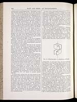
minor points are to be noted. In the first instance it
should be observed that in the instrument used the
disposition of the deflector systems is as in Fig. 1. The
change of field during the time occupied by an electron
in traversing the paths between either pair of deflectors,
or from the one system to the other, may be neglected,
since the total path xy is executed in 0·0015 micro-
second, corresponding to a phase angle of ½° at a
frequency of 1 million per second, so that no error is
introduced from this cause, even at the shortest commer-
cial wave-length now in use. For still higher frequencies
the re-design of the oscillograph to reduce this time-lag
to negligibility does not appear to present serious
difficulty.
A second point arising from the same feature of the
tube design is that whilst the angular deflection produced
by unit E.M.F. in the two systems is the same, the
plates producing horizontal deflection are nearer the
screen than are those producing vertical deflection,
the distance ratio being 1·08. There is consequently
an angular error which varies with azimuth, reaching a
maximum of 2¼° around the 45° points. As this source
of error is independent of amplitude and frequency, a
permanent scale correction is readily applied when
necessary. Again the error is not inherent in the
system, but is incidental to the particular instrument
used. In any case it can be compensated by a method
to be mentioned later.
In cases, such as the study of atmospherics, in which
there is no possibility of even a rough check on the
faithfulness of the indications, it is desirable to eliminate
even remote possibilities of error. For this reason the
installation at Ditton Park, to be described, is by no
means the simplest or cheapest that can he realized
within the scope of the general principle of making an
ionic beam the self-setting moving element of the
goniometer. It is, however, based on circuits which
most completely satisfy the requirements of symmetry
and freedom from risk of unequal amplification of the
component electromotive forces.
The circuit of this typical installation is represented
in Fig. 2. The receptive system comprises two loops
in two vertical planes intersecting at right angles along
a line bisecting the horizontal sides of each loop. To
ensure freedom from “antenna effect” or “vertical,”
the mid-points of these horizontal sides are all connected
to earth, as is also the anode of the oscillograph. The
tuning devices—loading inductances if required, and
tuning condensers—are split and arranged symmetri-
cally on either side of the central earth lead. There are
consequently, in each main loop, two tuned half-loops,
the tuning of each half being nearly independent of the
tuning of the other. Carrying still further the provision
for complete symmetry, special oscillographs have been
obtained in which each deflecting plate is separately
terminalled. It will be noted that in the standard
pattern of oscillograph two of the plates are joined
directly together and to the anode, whilst the other
two, one of each pair, are joined to the anode through
external resistive paths, so that complete symmetry is
not attainable with this form of tube.
[NLS note: a graphic appears here – see image of page]
FIG. 1.—Deflecting plates of cathode-ray oscillograph.
In the case of strong signals the oscillograph deflecting-
plates may be connected directly across the tuning
condensers as shown in. Fig. 2. For weaker signals the
general scheme of single-stage or multiple-stage amplifica-
tion is illustrated in Fig. 3. Since the load impedance
of the oscillograph, with its plate-to-plate capacity of
about 10 µµF and its gaseous conduction path of about
2 megohms, is high, the conditions are especially suitable
for “voltage amplification” by a resistance-capacity
amplifier employing triodes of high voltage factor.
It will be seen from Fig. 3 that symmetry is main-
tained by using a circuit of the so-called “push-pull”
type, in which, (considering only one stage), the filaments
- © National Library of Scotland 2009
- NLS home page
- Digital library